Assembling the Collector
(Use Enclosure Hardware Set, see Figure 7 and Product Package
Hardware, see Figure 3)
Note: The Enclosure Fabric is intentionally a tight fit. Assembly is
much easier when you perform the following procedures in order.
Tools Needed:
• 7/16" Deep Socket with Ratchet
• 7/16" Wrench
• 1/2” Deep Socket with Ratchet
• 1/2" Wrenches
• 9/16” Deep Socket with Ratchet
• 9/16” Wrench
• Hammer
Installing the Inner Link Assembly
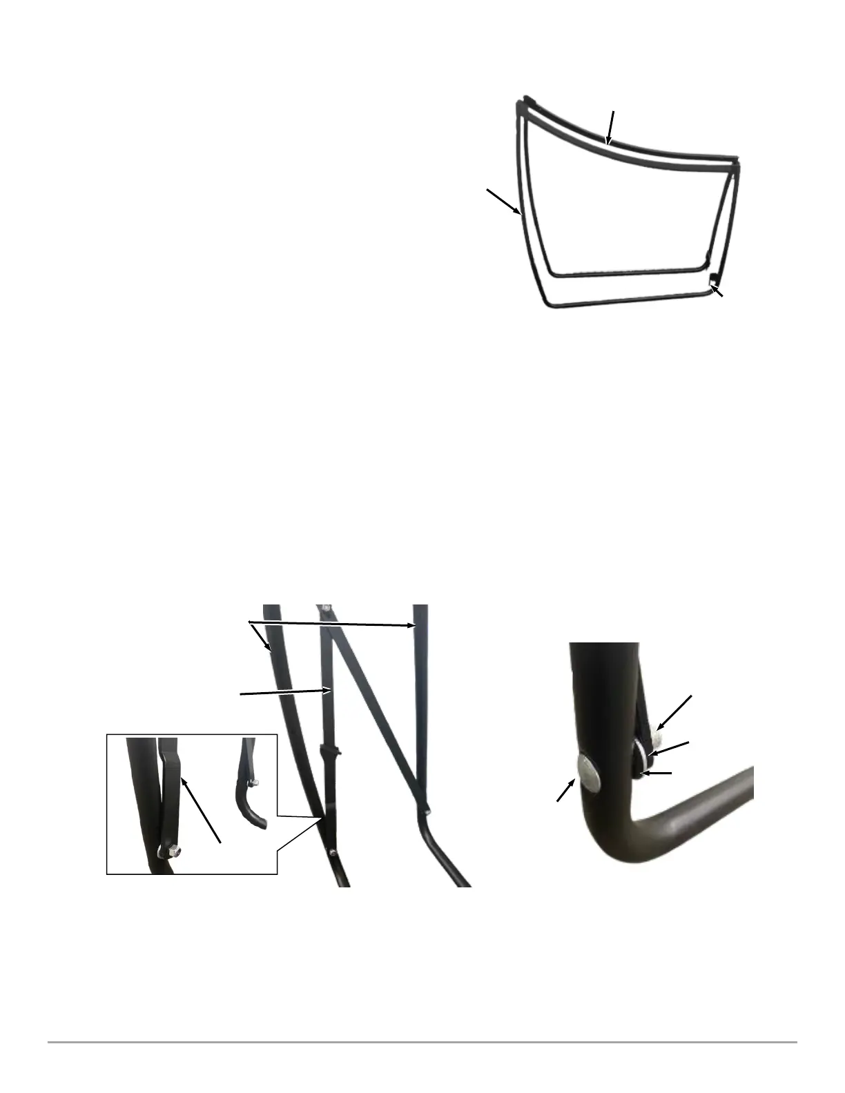
1. Remove any bubble wrap packaging from each Tube Frame and stand up both the LH and RH Tube Frames against a wall,
making note of the Pin Orientation shown (Figure 21).
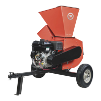
2. Orient the Inner Link Assembly onto the Tube Frames with the jogged bent link as shown (Figure 22).
3. Secure the links with hardware found in the Product Package (Figure 3) by inserting two carriage bolts (Bolt, C-Head, 5/16-
18 X 1.75) through the tube, followed by two washers (Washer-Flat 5/16 USS), the scissor links and then two lock nuts (Nut-
Lock Nylon 5/16-18) as shown in (Figure 23).
4. Tighten the lock nuts using a 1/2" Wrench just enough to engage the nylon end on the nuts. Making sure the carriage bolt is
seating correctly in the square tube hole. Do not over tighten, as the scissor links need to be able to rotate freely once
secured.
 Loading...