Commissioning
30 to 120m and 100 to 200m transmitters
• Connect the Hand Held Terminal and check that the signals from the receiver
are being displayed. If they were absent it would indicate that the digital link
from the receiver was not connected, usually due to a wiring fault. Also look
into the transmitter lens to check it is ashing at the correct, irregular rate
of four per second. A regular twice per second would indicate inadequate
voltage at the supply or excessive voltage drop in the supply cables.
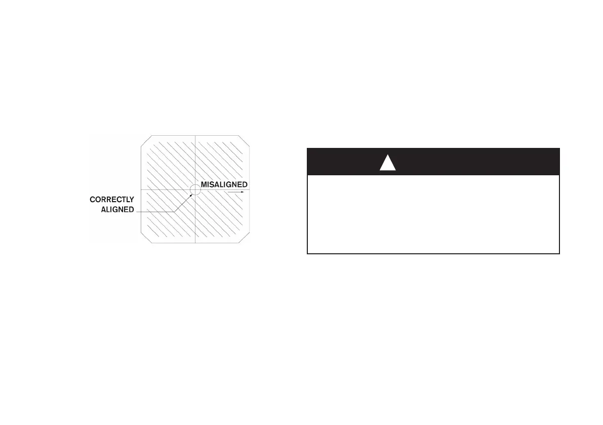
• At the left of the alignment screen the transmitter ‘target’ indicates the
degree of misalignment but not (unlike the receiver) its direction:
• First move the transmitter around to be sure you have found the strong
central peak in signal. Make slow adjustments, rst vertically then horizontally,
to maximise the signal strength. The nal horizontal adjustment moves the
circle from right to left, until the display matches the diagram. Tighten the
eight screws progressively in rotation to avoid losing the alignment. The
transmitter and connector covers can now be replaced.
Step 3: Final receiver alignment
• Check the receiver target display is correct. Both transmitter and receiver
displays should now be centred. If not repeat steps 1 and 2. If correct fully
tighten the eight receiver socket head screws.
Step 4: The zeroing procedure
• Press any key to enter RX ALIGN + ZERO menu, then select ‘ZERO’. A
message is displayed: ‘SAFETY WARNING’ Are you sure beam path is free
of gas?
• If you are sure there is no gas present select ‘YES’ otherwise press any
other key to abort zero. Once ‘YES’ is pressed the Hand Held Terminal will
display a count down from 32 to 1. (At the same time the analogue output will
increase to 20mA and ramp down to 4mA).
• Observe the Hand Held Terminal display until ‘ZEROING DONE’ is displayed
at the bottom of the screen.
• Turn o the Hand Held Terminal by pressing any two buttons together and
disconnect.
WARNING
If the control equipment fails to indicate 100%LEL
at the start of the zeroing procedure it indicates
that the resistance in the 4-20 mA current-loop is
too high. It is essential to investigate such a fault,
which could cause under-reading of gas.
!
Step 5: Verication with test sheets
• Hold a stack of ve immediately in front of the receiver lens. Verify from
the Hand-Held Terminal screen and from the control equipment that the
complete system responds correctly, as if to gas.
• If the reading is o scale, remove sheets one by one until it is on scale.
• Record the mean reading, together with the serial numbers of the transmitter,
receiver and test sheets for future reference.
Recording the test sheet readings enables you to check subsequently that the
response to gas has not been aected in any way. You may also wish to introduce
the test sheets one by one to check correct operation of the control equipment at
intermediate readings. If required, similar checks can be carried out with real gas
using the Gas Check Kit GCK400.

 Loading...