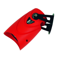
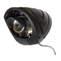
The Draeger Flame Detector FD 10 Range is a device designed to monitor and detect fire or flame in a given environment, triggering necessary control actions upon detection. It is specifically intended for use in areas that may contain potential explosive atmospheres.
Function Description
The flame detector operates by sensing the presence of flames. When power is initially applied, the device undergoes a self-test and system initialization period of approximately thirty seconds. During this time, an optical and hardware check is performed. If the device functions correctly, a green LED illuminates, indicating it is ready for fire detection. In case of a hardware or optical failure, a yellow LED will illuminate, signaling a problem that requires operator intervention. A red LED indicates that a fire hazard has been detected.
The detector generates a 0-20mA signal to indicate its status, which can be monitored during installation and maintenance. This signal, along with the LED indicators, provides a comprehensive overview of the device's operational status. The FD10 range includes different models: 1300 IR Flame Detector, 1700 UV Flame Detector, and 2300 UVIR Flame Detector, each with specific detection capabilities and corresponding mA outputs for various statuses (Fault, Optical Fault, Normal, Warning, Fire, IR Presence, UV Presence).
Important Technical Specifications
- Ambient Conditions: -40°C to +60°C (-40 to +140°F), 91.5 to 105.5kPa, 0-99% relative humidity.
- IP Rating: IP 67, NEMA 4X (with O-rings fitted).
- Supply Voltage: 18 to 32VDC.
- Flame 1300: Current consumption 160mA quiescent state at 24 VDC (maximum 230mA).
- Flame 1700: Current consumption 160mA quiescent state at 24 VDC (maximum 180mA).
- Flame 2300: Current consumption 175mA quiescent state at 24 VDC (maximum 240mA).
- Dimensions: Approximately 275 x 155mm.
- Weight:
- Aluminium Housing: Less than 3.5kg (7.7lbs).
- Stainless Steel Housing: Less than 5kg (11lbs).
- Regulatory Approvals:
- ATEX: Certificate Number: ITS 04 ATEX 11807; ATEX: II 2 G EEx d IIC; EEx d [ia] IIC T6 (Tamb -50°C to +60°C); EEx d [ia] IIC T5 (Tamb -50°C to +70°C).
- IECEx: Certificate Number: ITS 04.0003; IEC Ex d: II 2 G EEx d IIC; EEx d [ia] IIC T6 (Tamb -50°C to +60°C); EEx d [ia] IIC T5 (Tamb -50°C to +70°C).
- FM/CSA: Class I, Groups A, B, C, D; Class I, Zone 1, Groups IIA, IIB, & IIC; Ex d II C; T6/T5; -40°C ≤ Tamb ≤ +60°C / +70°C.
- Operating Distance: 0.1m² (1 sq. foot) N-heptane fire or Propane flame fire at 18m and respond within 30 seconds. 5 inch (800W) propane flame at 1.44m (4 feet 9 inches) and respond within 30 seconds.
- Torque Settings:
- Housing Screws: 15 Nm.
- Back Cover Locking screw: 0.8 Nm.
- Front Cover Locking screw: 0.8 Nm.
- Reliability - Mean Time Between Failure (MTBF): ≥ 100,000 Hours.
- Response Time to Fire:
- Flame 1300: 3.5 seconds.
- Flame 1700: 1 second.
- Flame 2300: 3.3 seconds.
Usage Features
- Installation: Only trained service personnel (e.g., Draeger Safety service personnel) should install the flame detector, adhering to local regulations. The device should be mounted on vibration-free structures, ensuring a clear view of the area to be protected. The sensor angle should always be downward, at a minimum of 10° - 20°.
- Electrical Installation: Wiring must comply with national regulations for electrical devices and, if applicable, for potentially explosive atmospheres. Power must be switched off before connecting any cabling. The detector requires a 24 Volts DC nominal supply voltage and provides an isolated 4-20mA output and three relays (alarm, fault, spare).
- Terminal Connections: The device features a built-in terminal block with 37 terminals for various output connections, including power, 4-20mA output, alarm relay, fault relay, spare relay, manual test activation, and cable screen linking. Each terminal can accept suitably crimped/ferruled 2.5mm² core wires. An external earth (ground) connection for 4mm² wires is also provided.
- Manual Test: A manual optical test can be activated by connecting 24 Volts to pin 15 of the terminal block.
- Explosion Protection: The device has explosion-protection approvals for use in gas/vapor-air mixtures of combustible gases and vapors under atmospheric conditions. These approvals are not valid for oxygen-enriched atmospheres. Unauthorized opening of the enclosure voids the explosion-protection approval. When installed in certified areas (NEC 500 Class 1 Div 1 or NEC 505 Class 1 Zone 1), it must use type MC-HL cable (Metal Clad for Hazardous Locations).
Maintenance Features
- Regular Inspection and Servicing: The device must be inspected and serviced by experts at regular intervals, with records kept. Repairs and general overhauls should only be carried out by appropriately trained service personnel. Draeger Safety recommends a service contract and the use of authentic Draeger spare parts.
- Automatic Optics Test: The Draeger Flame Detector FD10 Range performs an automatic optics test every 30 minutes, which typically takes about 10 seconds.
- User Serviceability: The Draeger Flame Detector FD 10 Range contains no user-serviceable parts. In the event of a suspected failure, the unit should be returned to Draeger Safety UK Ltd. No attempt should be made to disassemble the units in hazardous areas.
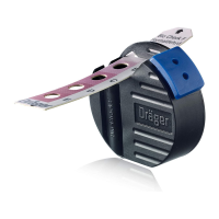
- Cover Replacement: When replacing the detector front cover assembly, ensure the calibration bar in front of the lens is horizontal. Hand-tighten the front cover, then back it off a maximum of half a turn until the two locking screws align with the detector housing. Tighten both locking screws to the specified torque using a 2mm hexagon key.
- Cleaning: The only servicing requirement is to measure the 0-20mA output and correlate readings with the expected LED color, and to ensure the lenses are clean. The detector's outer cover (weather shield) is molded ABS/polycarbonate and is not antistatic; therefore, it should be cleaned only with a damp cloth.
- Lubrication: Before replacing the terminal compartment cover, ensure the threads are lightly lubricated using suitable non-setting silicone grease. Hand-tighten the terminal cover, then tighten the locking screw with a 2mm hexagon key. The terminal compartment cover and front cover threads must be lightly lubricated with non-setting grease prior to re-assembly.
- Functional Test: A function test using a suitable test torch should be carried out regularly.
- Disposal: From August 2005, EU regulations apply to the disposal of electrical and electronic devices. Since the device is not registered for private household use, it cannot be disposed of as special household waste. For disposal, it should be returned to your national Draeger Safety Sales organization.