

D
dominique10Sep 23, 2025
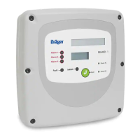
What does a calibration failure message on my Dräger Controller mean?
- RRuth GonzalezSep 23, 2025
If you see a calibration failure message on the screen of your Dräger Controller, it indicates a potential fault with the remote sensor transmitter. Check and repair the transmitter wiring and recalibrate.