Do you have a question about the Dräger REGARD-1 and is the answer not in the manual?
Details on regular maintenance, servicing, and safety precautions for the device.
Critical warning against using the device in potentially explosive atmospheres.
Statement on liability transfer for device function based on servicing and usage.
Specifies the intended use for the Regard-1 controller with 4-20 mA transmitters.
Details the intended use for the Regard-1 controller with SE Ex measuring heads.
Clarifies that ATEX marking does not imply 'explosion proof' status.
Information on additional tests and approvals conducted for the device.
Specific safety conditions related to the EC type examination certificate.
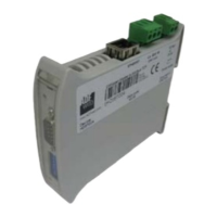
Overview of available device versions and optional features like the options circuit board.
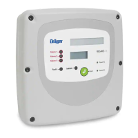
Visual guide to the main internal components of the Regard-1 controller.
Identifies and describes the purpose of various terminals and connectors on the main board.
Locates and explains the function of potentiometers for alarm and display settings.
Detailed list of terminal numbers and their corresponding functions for field device connections.
Crucial warning against connecting AC and DC power supplies simultaneously.
Illustrates normal and negative gas level readings on the display.
Explains indicators for readings below or above the measuring range.
Describes the differences between display board firmware versions V1 and V2.
Highlights the function of the buzzer for local audible alarms.
Identifies Pellistor board controls (SW1, VR1, VR2, VR3) and their functions.
Details the features provided by the options circuit board, like TWA relay and datalogger.
Instructions for fitting the options circuit board and its output connections.
Pinout details for RJ11 socket and RS 232 Sub D connector for data logger output.
Information on data format, rate, and procedure for resetting the TWA value.
Considerations for selecting an appropriate installation location.
Identification of mounting points on the enclosure for installation.
Instruction to use a hole cutter for making cable entries.
Diagram and notes for connecting a two-wire 4-20 mA transmitter.
Guidance for connecting a three-wire 4-20 mA transmitter (source output only).
Recommendation to use cable with braided copper screen for safety barrier connections.
Warning against connecting the sensor while the controller is powered.
Specifies maximum allowed cable resistance based on cable cross-section for SE Ex sensors.
Describes the normal state of A1, A2, TWA, A3, Fault, and Inhibit relays.
Specifies that the fault relay is normally energised when no fault is present.
Note recommending the use of braided copper screen cable for digital outputs.
Recommendation to use braided copper screen cable for the remote reset input.
Instructions on how to set the display measuring range using SW1 on the display board.
Note directing users to the transmitter's manual for calibration details.
Steps for performing zero calibration on a 4-20 mA unit.
Methods for performing span calibration on a 4-20 mA unit.
Table correlating gas concentration percentage to voltage across TP1 & TP2.
Mapping of transmitter signal (mA) to voltage and display readings for calibration.
Note directing users to the measuring head's manual for calibration.
Procedure for setting the sensor current using the SW1-A switch.
Warning against connecting the sensor while the controller is powered.
Procedure for setting the amplifier gain range using SW1-B, -C, and -D.
Warning not to change the position of switch SW1-A during calibration.
Steps for applying calibration gas and adjusting VR3 on the pellistor board.
Description of alarm modes: rising or falling, latching or non-latching.
Configuration of the A1 alarm using SW1 switches on the main circuit board.
Configuration options for the fault alarm relay.
Emphasizes using relay status and DVM for safety decisions, not display readings.
Procedure for setting the A1 alarm threshold using potentiometers.
Procedure for setting A2 and A3 alarm thresholds using potentiometers.
Recommendation against alarms below 10% and above 60% for flammable gas detection.
Information about the fixed fault alarm threshold for SE Ex units.
Guidance on regular checks and servicing intervals for the controller.
Information on periodic recalibration requirements for sensors.
Instructions for maintaining batteries fitted to the control unit.
Overview of the fault finding section and common issues.
Detailed remedies for specific faults encountered with the device.
Explanation of the device's watchdog reset behavior during normal operation.
Detailed physical and electrical specifications for the Regard-1 4-20 model.
Detailed physical and electrical specifications for the Regard-1 SE Ex model.
Information on environmental conditions for storage and operation.
Details on device approvals, CE marking, and RS-232 data logger output.
List of part numbers for the Regard-1 4-20 and SE Ex units.
Part numbers for accessories and spare components for the device.
Information on the EC Type Examination Certificate, including directives covered.
Details on the Essential Health and Safety Requirements met by the equipment.
References to the test report and specific conditions for safe use.
Details on equipment marking and the issuing certification body.
Description of the control unit's subject and type.
Information on parameters and the test assessment report.
Statement confirming the correctness of the translation from the German original.
Details of the supplement to the EC-type examination certificate and test report references.
Further information on special conditions for safe use.
Items not included in the scope of the type-examination.
Formal declaration of conformity and details of the issuing body.
Examples of front panel labels for Methane, Hydrogen Sulphide, and Carbon Monoxide.
Examples of front panel labels for Ammonia and Oxygen.
| Brand | Dräger |
|---|---|
| Model | REGARD-1 |
| Category | Controller |
| Language | English |