Configuration and calibration
Issue 5 - June 2005 Page 35 of 64 Pages
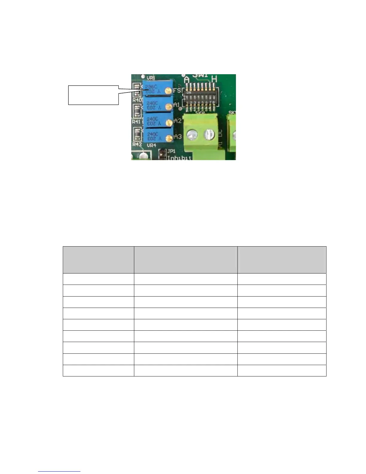
Location of FS (span adjust) potentiometer:
When simulating a gas level:
• If possible, adjust the output of the transmitter to 20 mA or to a value between
12 mA and 20 mA.
• Adjust potentiometer FS on the main circuit board until the voltage across TP1 and
TP2 corresponds to the transmitter output. If the controller has a display, confirm
that the reading is correct.
Transmitter signal
(mA)
Voltage across
TP1 & TP2 (V)
Display reading
(0 – 100 range*)
12 2.4 50
13 2.6 56
14 2.8 63
15 3.0 69
16 3.2 75
17 3.4 81
18 3.6 88
19 3.8 94
20 4.0 100
* Scale for different measuring range
FS: span adjust