Configuration and calibration
Issue 5 - June 2005 Page 42 of 64 Pages
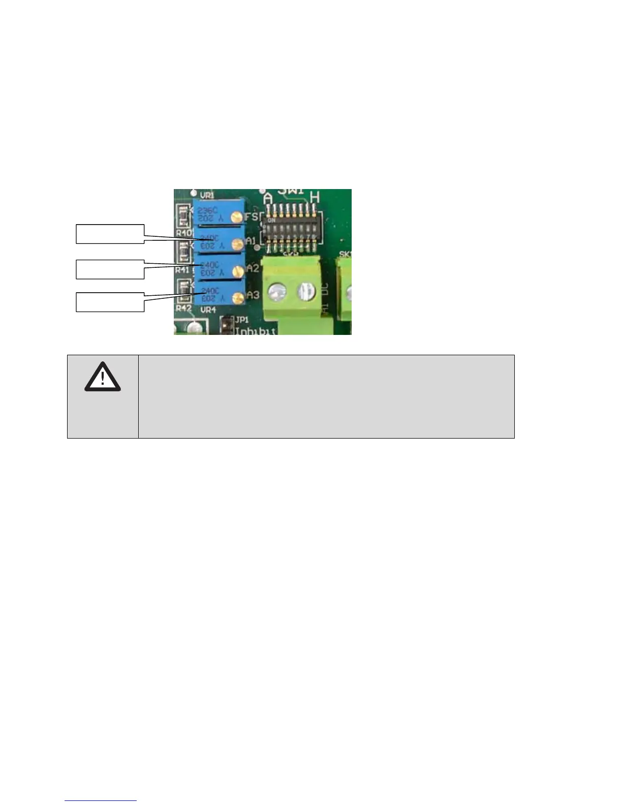
Setting alarm thresholds on 4-20 units
Use the potentiometers marked A1, A2 and A3 on the main circuit board to set the
alarm thresholds:
WARNING!
For safety relevant decisions only use status of Alarm/Fault LEDs
and relays. Do not use display reading. For calibration and
adjustment of alarm set points use DVM between test points TP1
and TP2 only.
To set the alarm levels you must simulate a gas signal. You can do this
• using a potentiometer that can be varied from 1200 to 6000 ohms
• by directly controlling the output of the transmitter
• using a 4-20 mA loop calibrator