Configuration and calibration
Issue 5 - June 2005 Page 38 of 64 Pages
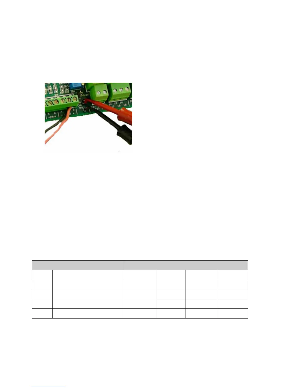
Zero calibration
• Connect a voltmeter across TP1 and TP2 on the main circuit board.
• Make sure that the ambient air is free of measured gas and other interfering gases
which could influence the sensor.
• Turn VR1 on the pellistor board until the voltage across TP1 and TP2 is
800 mV ± 20 mV. To increase the reading, turn VR1 anti-clockwise.
• If the controller has a display, verify that it reads zero.
Calibrate span
1. Calibrate sensitivity range
Set the amplifier gain range using switches SW1-B, -C and -D.
Range SW1
No. Sensitivity A B C D
1
10 – 60 mV
•
ON OFF OFF
2
60 – 110 mV
•
OFF ON OFF
3
110 – 160 mV
•
OFF OFF ON
4
160 – 220 mV
•
OFF OFF OFF