Configuration and calibration
Issue 5 - June 2005 Page 39 of 64 Pages
WARNING!
Do not change the position of switch SW1-A.
For new Dräger Ex sensors, range 3 (110 – 160 mV) should work for most gases. If,
during calibration, the gas reading does not reach the required value use a lower-
numbered sensitivity range. If the display reading is too high use a higher-numbered
sensitivity range.
2. Apply calibration gas
Use a calibration gas with concentration between 40% and 60% of the measuring
range.
• Apply gas using calibration adaptor at 0.5 l/min flow rate.
• Allow display reading to settle (about 2 to 3 minutes)
• Adjust VR3 on the pellistor board until the voltage across TP1 and TP2 corresponds
to the concentration of the calibration gas.
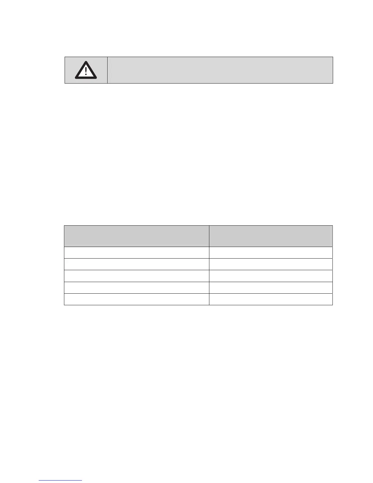
Gas concentration
(as % of measuring range)
Voltage across
TP1 & TP2 (V)
40 2.08
45 2.24
50 2.40
55 2.56
60 2.72
• If the device has a display, verify that the display reading corresponds to the gas
concentration.
Configuring alarms
There are three gas alarms. Each alarm can be set to be
• rising or falling
• latching or non-latching