Configuration and calibration
Issue 5 - June 2005 Page 34 of 64 Pages
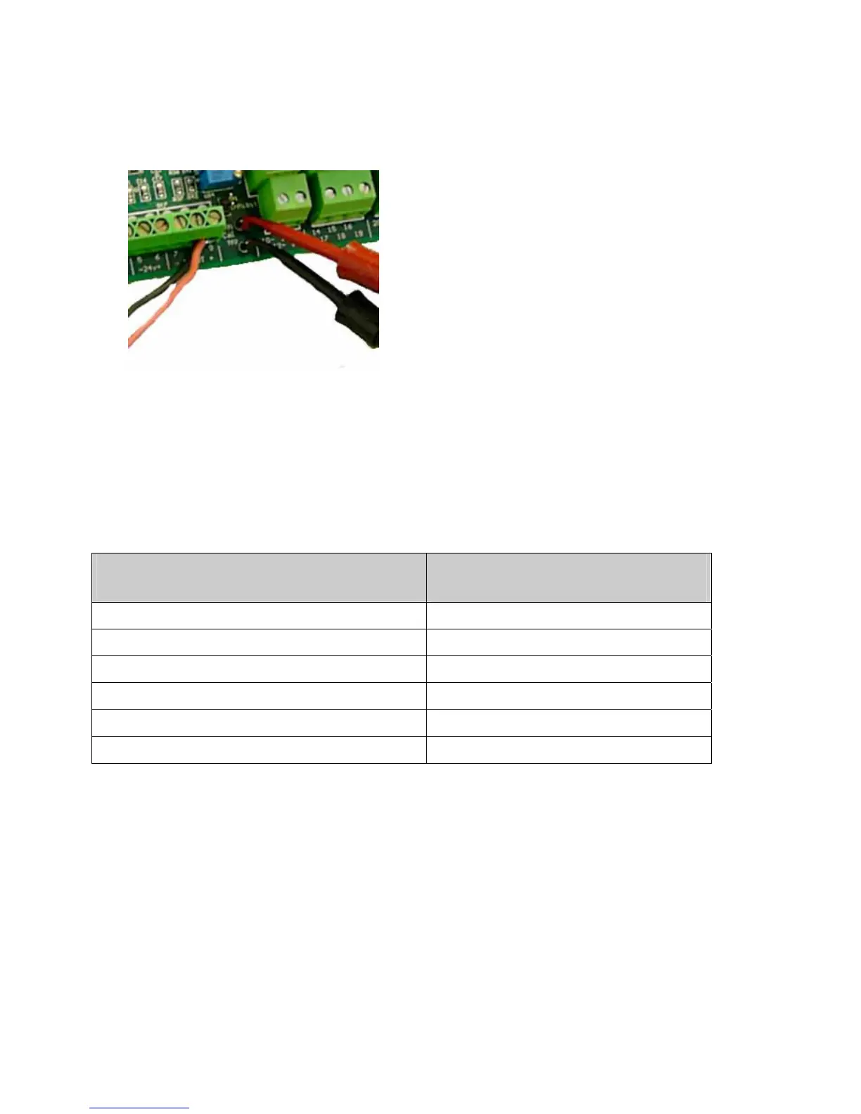
• Connect a voltmeter across TP1 and TP2 on the main circuit board:
If applying calibration gas to the transmitter:
• Apply calibration gas to the transmitter. Use a gas concentration that is between
40% and 90% of measuring range. The transmitter must be correctly calibrated.
• Adjust potentiometer FS on the main circuit board until the voltage across TP1 and
TP2 corresponds to the gas concentration. If the controller has a display, confirm
that the reading is correct.
Gas concentration
(as % of measuring range)
Voltage across
TP1 & TP2 (V)
40 2.08
50 2.40
60 2.72
70 3.04
80 3.36
90 3.68