Configuration and calibration
Issue 5 - June 2005 Page 46 of 64 Pages
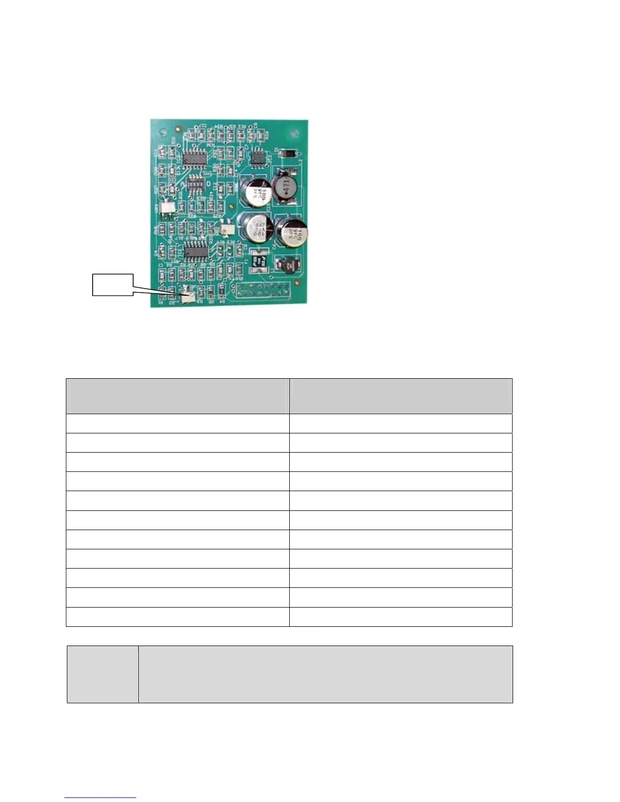
Use VR1 on the pellistor board to simulate a sensor signal.
Measure the voltage across test points TP1 and TP2 to determine the alarm threshold.
If the device has a display you can use the display reading to give additional
confirmation that the alarm set points are correct.
Alarm threshold
(% of 0 – 100 range)
Voltage across TP1 & TP2 (V)
10% 1.12
15% 1.28
20% 1.44
25% 1.60
30% 1.76
35% 1.92
40% 2.08
45% 2.24
50% 2.40
55% 2.56
60% 2.72
NOTE
Alarms below 10% and above 60% of measuring range are not
recommended for flammable gas detection.
VR1