Do you have a question about the DRAKE TR-4C and is the answer not in the manual?
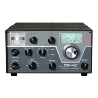
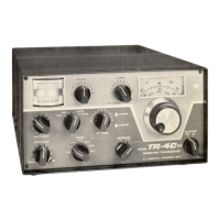
Provides a general overview of the TR-4C transceiver's capabilities and features.
Details the scope of information provided in each chapter of the manual.
Lists the technical specifications of the TR-4C transceiver.
Instructions for carefully removing the unit from its shipping carton and checking for damage.
Guidance on selecting a suitable location for the TR-4C, emphasizing air circulation and access.
Specific considerations for installing the TR-4C in a mobile vehicle environment.
Details the power supply needs for mobile installation, specifying the DC-4 unit.
Instructions for physically mounting the TR-4C using a mobile mounting kit.
Guidance on connecting the antenna to the TR-4C for mobile operation.
Recommendations for connecting a speaker, advising against using the car radio speaker.
Instructions for connecting a suitable microphone for optimal performance.
Guidance for setting up the TR-4C for stationary or base station use.
Details the power supply needs for stationary installation, specifying the AC-4 unit.
Illustrations and options for adjusting the viewing angle of the transceiver.
References figures for electrical connections with various recommended accessories.
An overview of front panel controls and rear/side connectors.
Explains the function of the Mode switch for SSB, CW, and AM operation.
Describes the operation and limitations of the noise blanker switch.
Details the dual-disc VFO dial and its frequency indication and calibration.
Provides a caution and general guidance before attempting tuning procedures.
Instructions for setting the PA bias to the correct value before operation.
Step-by-step procedure for tuning the transmitter for optimal output and matching.
Guide to operating the transceiver in Single Sideband mode, including control settings.
Instructions for operating the TR-4C in Morse Code (CW) mode.
Instructions for operating the TR-4C in Amplitude Modulation (AM) mode.
Guidance on operating the transceiver near amateur band frequency edges.
Procedures for connecting and operating the TR-4C with an external linear amplifier.
Specific guidance for novice operators using the TR-4C on amateur bands.
A general overview of the TR-4C transceiver's design and capabilities.
Detailed explanation of the receiver's internal circuitry and signal path.
Detailed explanation of the transmitter's internal circuitry and signal path.
Information on factory service, repairs, and authorization procedures.
Step-by-step instructions for removing the top cover of the transceiver.
Step-by-step instructions for removing the bottom cover of the transceiver.
Guidance on replacing vacuum tubes, including specific tube types and alignment.
General advice for troubleshooting issues and when to seek professional service.
Lists the necessary test equipment required for alignment and maintenance.
An introduction to the alignment procedures for the TR-4C.
Procedure for aligning the internal crystal calibrator.
Procedure for aligning the 9.0 MHz oscillator circuit.
Procedure for aligning the injection crystal oscillators.
Information regarding the VFO adjustment and factory calibration.
Procedure for aligning the injection coupler circuits.
Procedure for peaking RF tune and adjusting IF transformers for receiver IF alignment.
Procedure for aligning the balanced modulator and carrier balance circuits.
Procedure for adjusting filter matching transformers for optimal S meter readings.
Procedure for neutralizing the Power Amplifier (PA) stage.
Procedure for neutralizing the transmitter IF stage.
Procedure for adjusting the S meter to the correct calibration point.
| Brand | DRAKE |
|---|---|
| Model | TR-4C |
| Category | Transceiver |
| Language | English |