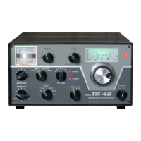
FRONT PANEL CONTROLS
1.
2.
3.
4.
5.
6.
7.
8.
S meter: Indicates relative level of received sig-
nals. Indicates transmitter AGC when trans-
mitting.
Plate meter: Indicates plate current in the final
amplifier. Indicates relative RF power when
LOAD control (6) is pushed in.
PLATE control: Tunes power amplifier
pi-
network circuit for resonance.
RF TUNE control: Peak tunes the receiver RF
amplifier, the transmitter driver grid and plate
tuned circuits.
UPPER sideband indicator lamp: Glows when
upper sideband is selected.
LOAD control: Matches the TR-4C to the
impedance of the antenna. Push in to display
relative R F power on plate meter (2).
VFO dial: Displays portion of operating fre-
quency from zero to 600 kHz. Reading must
be added to BAND switch frequency setting
for complete operating frequency.
VFO control: Adjusts frequency setting of
dial (7).
9.
IO.
11.
12.
13.
14.
15.
16.
VFO indicator lamp: Glows only when TR-4C
VFO is operating.
BLANKER switch: Provides on/off control for
R. L. Drake’s Model 34-PNB Noise Blanker
(an accessory).
SIDEBAND switch: Selects upper or lower
sideband and lights appropriate indicator lamp
(5 or 12).
LOWER sideband indicator lamp: Glows when
lower sideband is selected.
BAND switch: Selects the desired amateur
band.
Mode switch: Selects the desired mode of oper-
ation. In CAL position, it switches on the 100
kHz crystal calibrator (operable in transmit or
receiver mode).
RCVR GAIN control: Dual control. Knob con-
trols the receiver audio level, and provides a
power on/off control at the extreme counter-
clockwise position.
Lever controls the maxi-
mum RF gain of the receiver.
XMTR GAIN control: Adjusts the microphone
gain on AM and SSB. In CW mode it adjusts
the RF drive.
3-3