CHAPTER
III
OPERATION
3-l. GENERAL.
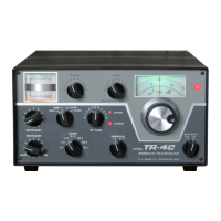
Figure 3-l illustrates and describes all front panel
controls and indicators on the TR-4C Transceiver.
Controls and connectors located on the rear and
sides of the unit are described under “other
controls” below. Rear chassis connectors are identi-
fied in figure 2-2.
3-2. MODE SWITCH. In the SSB position, the
receiver portion functions until the transmitter is
energized either by talking into the microphone or
actuating the microphone push-to-talk switch. The
transmitter then emits an upper or lower sideband
signal depending on the setting of the SIDEBAND
switch. In the X-CW position, the receiver portion
functions until the key is closed. The TR-4C then
goes into the transmit mode, a CW
sidetone
is
energized and the carrier is shifted approximately
1 kHz from the received frequency. The unit will
remain in transmit during CW keying and will return
to receive when keying is stopped briefly. NOTE:
The SIDEBAND switch must be in the X position
when the Mode switch is on X-CW or X-AM. It
should also be noted that if the relays fail to close
occasionally when the key is used, advance the
VOX gain (screwdriver adjust on the right side of
the chassis) until positive relay action is obtained.
In the X-AM position, a controlled carrier screen
modulator is incorporated for AM transmission and
a diode detector is used for AM reception. Transmit
and receive switching is accomplished by VOX or
push-to-talk as on SSB.
3-3. BLANKER SWITCH. The noise blanker may
be left on except when there is a strong signal
within
5
kHz of the received signal. A strong signal
which falls within the 10 kHz wide crystal filter in
the noise blanker, and outside the 2.1 kHz crystal
filter in the
TR-4C,
will operate the noise blanker
gate circuit causing distortion products. This limita-
tion in the noise blanker is caused by the necessity
of having a bandwidth in the blanker wide enough
to minimize stretching of noise pulses before blank-
ing. Usually this limitation is no problem under
normal operating conditions.
3-4. VFO DIAL. This dial consists
of
2 transparent
discs which display concentric scales and which
rotate at different speeds. There are 2 scales on
each disc. The upper scale on each disc is used for
all bands except 20 meters where the lower scale is
used. Zero to 100 kHz is indicated on one disc and
hundreds of kHz is indicated on the other. The
frequency of the operating signal is the sum of the
frequencies indicated by the BAND switch and the
VFO dial, for example:
BAND switch frequency
7.000 MHz
100 kHz dial
.200
1 kHz dial .072
Operating frequency 7.272 MHz
This dial may be calibrated over a short range by
the following procedure:
a.
b,
C.
Set the Mode switch to CAL.
Tune the
TR-4C
to zero beat with the nearest
100 kHz calibrator signal.
Hold the tuning knob stationary and rotate the
knob skirt until the dial displays the correct
frequency.
3-5. TUNING PROCEDURE.
CAUTION
Under no circumstances should operation
of the TR-4C be attempted until it is
connected to a proper antenna or a
dummy load. Always allow a two minute
warm up period after the TR-4C is
turned on before transmitting.
3-6. BIAS ADJUSTMENT. Before any type of
operation is attempted, it will be necessary to set
the PA bias to the correct value. Proceed as follows:
a. Turn on the TR-4C with the RCVR GAIN
control.
b. Rotate the XMTR GAIN control fully counter-
clockwise.
3-l