page 12 of 28
Foundation
™
for LED Panels
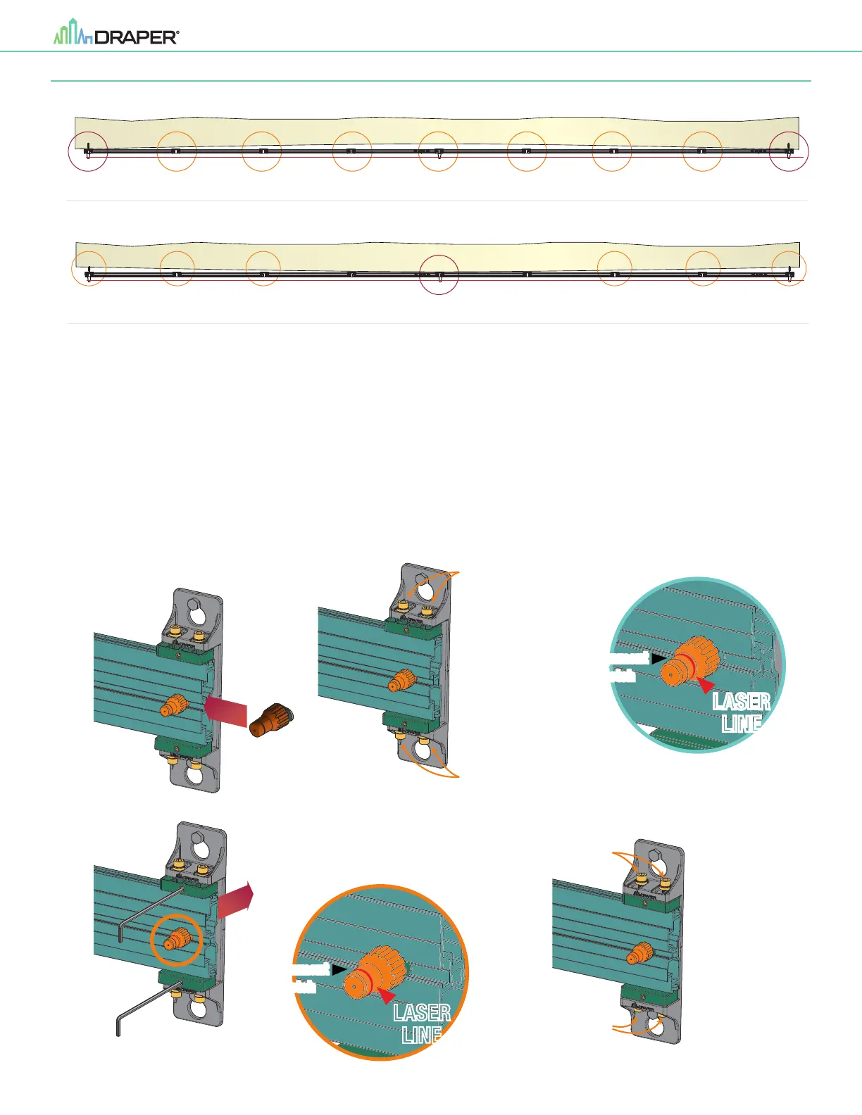
Section 6 - Adjusting and Aligning Horizontal Rails
1.
Position three (3) Plum Alignment Pins on each horizontal rail ensuring one is at the far left, center and far right.
2.
Using a 5mm Hex Wrench, loosen the four (4) locking screws on the top and bottom of each of the four (4) outer wall mounting brackets.
3.
Shine a laser level parallel to the wall with the laser intersecting the plum alignment pins.
4.
Using a 3mm Hex Wrench, turn the two (2) adjustment set screws on each wall mounting bracket to position the Alignment Notch with the laser line
(Please Note: when setting the plumb adjustment, the face of the horizontal rail must remain plump and not twisted).
5.
Once the Laser Line and all Alignment Pins are aligned, tighten the four (4) locking screws on the top and bottom each of the outer mounting bracket.
TOP VIEW - CONCAVE WALL
FRONT
VIEW
SIDE
VIEW
53.835”
(1367mm)
34.2”
(869mm)
BOTTOM
of Viewing Area
19.8”
(489mm)
Laser Line Laser Line
TOP VIEW - CONVEX WALL
FRONT
VIEW
SIDE
VIEW
53.835”
(1367mm)
34.2”
(869mm)
BOTTOM
of Viewing Area
19.8”
(489mm)
Laser Line Laser Line
LASER
LINE
Before
Adjustement
Alignment
Notch
Loosen
Adjustment
Screws
Loosen
Adjustment
Screws
LASER
LINE
After
Alignment
Notch
3mm Hex
Tighten
Adjustment
Screws
Tighten
Adjustment
Screws
 Loading...