DREHMO - MaticC Profibus DPV0/DPV1 Page 7 of 28
Complementary operating manual
3 Electrical connection
3.1 Mains connection (Standard)
Work on electrical equipment and electrical installation work on actuators must be
carried out by electricians or under supervision by fully qualified engineers, in
accordance with the valid electrical regulations.
Wiring should be carried out according to the enclosed wiring diagram. All control
cables shall be shielded to guarantee the electromagnetic compatibility of the
actuator. The main power cable need not be shielded.
The overcurrent protection of the actuator has to be installed inside the power
network. For rated values, see design data.
Pay special attention to the grounding of the actuator (refer to wiring diagram). Electrical
protection is not obtained until all covers are closed.
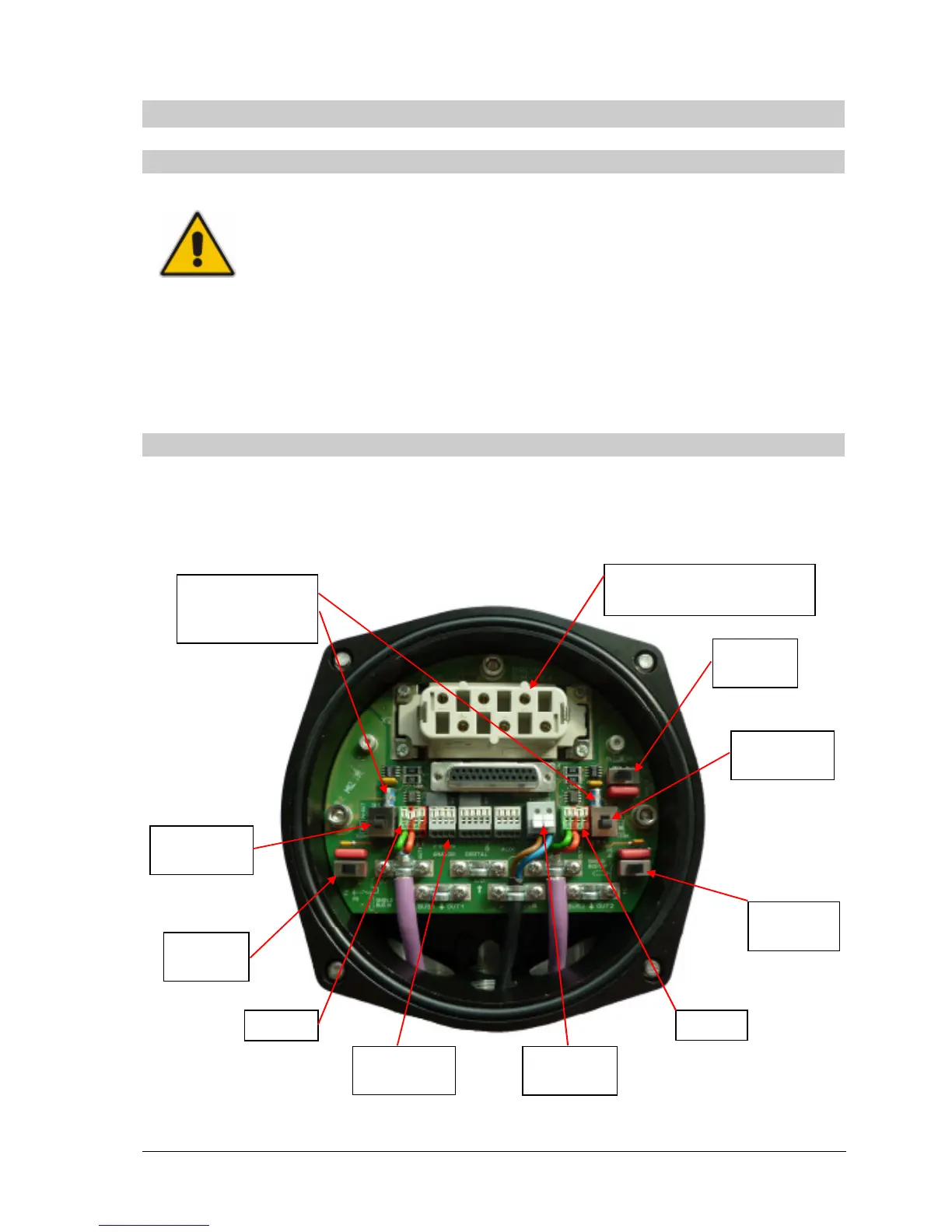
3.2 Bus connection (Standard)
Wiring is carried out according the wiring diagram supplied with the actuator. Locations of the
connection terminals and switches are shown in the following picture. The picture shows the
version for the redundant bus connection with overvoltage protection. Depending on the
configuration it is possible, that the components for BUS 2, the optional inputs or the overvoltage
protection do not exist.
Additionally to the electrical connection enabling/disabling the Profibus termination and the
grounding of the shield is done on the connection board.
BUS 1