DREHMO - MaticC Profibus DPV0/DPV1 Page 9 of 28
Complementary operating manual
Connection:
- Insertion of the PROFIBUS cable trough the cable glands
- The shielding clamps for the PROFIBUS cables have to be removed
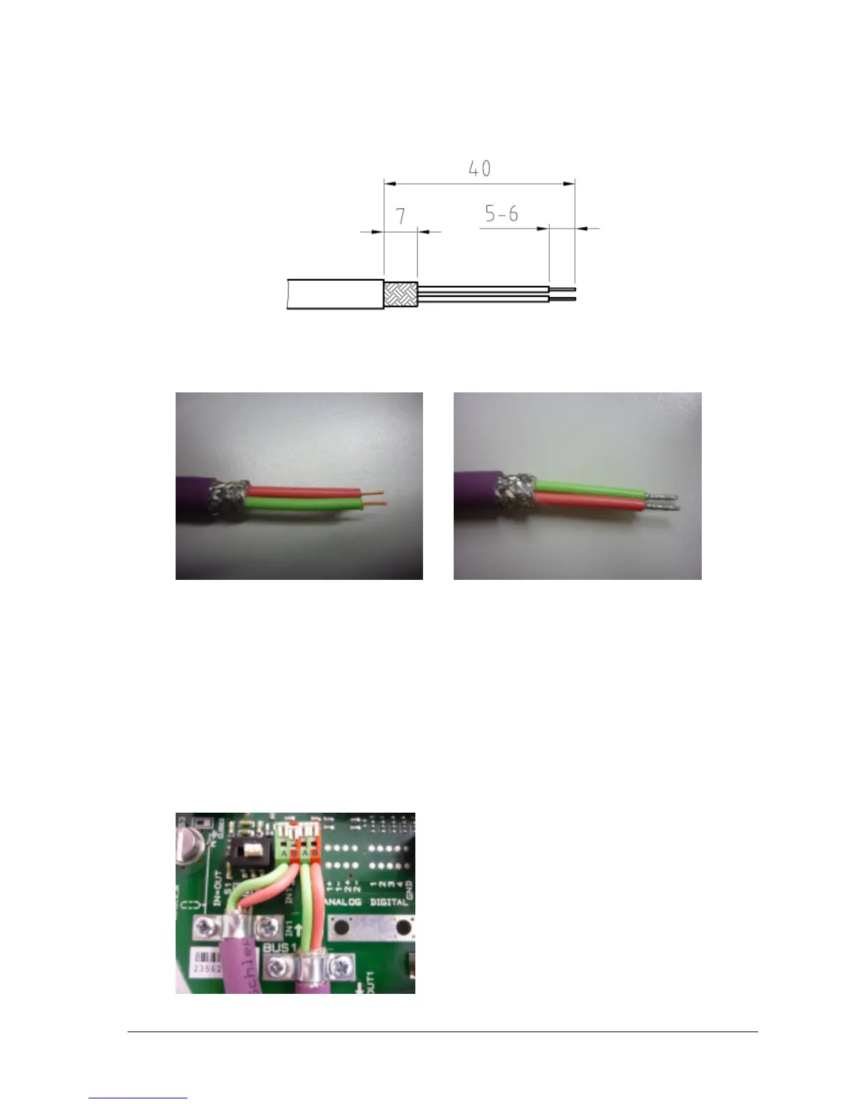
- The PROFIBUS cable and wires have to be prepared according the following drawing
all measurements in mm
Preparation of the PROFIBUS cable and wires
without ferrule with ferrule
Pictures:
PROFIBUS cable without ferrule and multi-conductor with ferrule
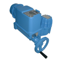
- In order to open the terminal contact, the slider has to be pushed forward or the contact
spring (in front of the slider) has to be pushed down with a screwdriver (blade width 2.5 to
3.5 mm)
- The PROFIBUS wire has to be inserted in an angle of approximately 40° relative to the
PCB board plane into the terminal. The slider has to be pushed backwards afterwards to
fasten the conductor (if a ferrule without plastic shroud is used, due to the commonly
ferrule length of approx. 7mm, the conductor isolation doesn’t immerge totally inside the
terminal inlet).
Picture: PROFIBUS terminals