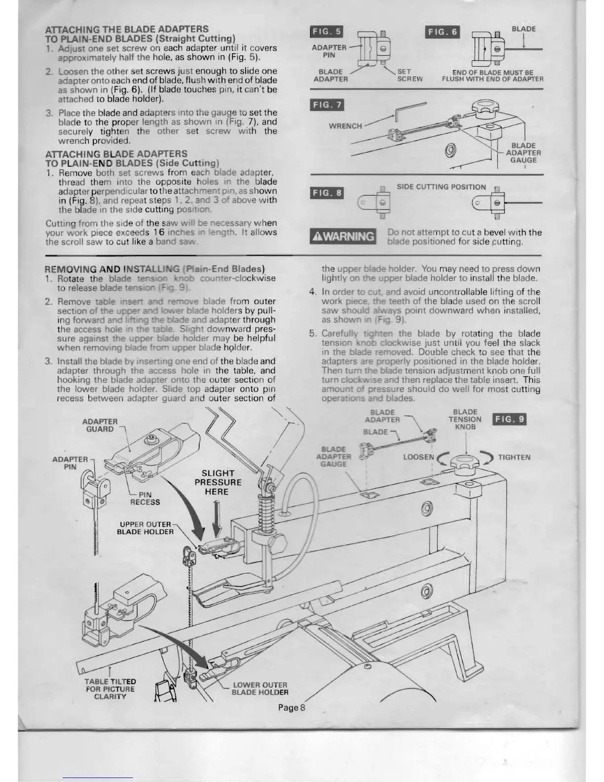
ATTACHING
THE
BLADE ADAPTERS
TO PLAI
-END
BLADES
(Straight
Cutting)
1. Just
one
set
screw
on each adapter until it covers
approximately half the hol
e,
as
shown
in (Fig. 5
).
2 oosen the
other
set screws ju
st
enough to slide one
adapter
onto
each end
of
blade, flush
with
end of blade
as
shown
In
(Fig. 6). (If blade touches pin,
it
an't be
attached to blade holder).
3 Place the blade and adapters Into the gauge to set the
blade to the prop
er
length as
shown
In
(Fig. 7). and
securely tighten the other set screw
wit
h the
wrenc
h provided.
ATTACHING BLADE ADAPTERS
TO PLAIN-END BLADES (Side
Cutting)
1. Remo
ve
both
set
screws from each 0
ade
adapter,
t
hr
e
ad
them IOta the opposite ales he blade
adapter perpendicular to the attachl"T'e •
p
...
as
sh
own
in
(F
ig. 8). and repeat
st
e
ps'.
2 an 3
of
above w ith
the blade in the side cuttlOg pos .
Cutting from the side
of
the s
aw
be
ec~ssary
wh
en
your
work
piece exceeds 1 6
inC
f!
fr
. It allo
ws
the scroll
saw
to cu like a
band
'I.i
~
'i.'
ADAPTERi
Q
PIN
Y-'
BLADE SET
END
OF
BLADE MUST
BE
ADAPTER
SCREW FLUSH WITH END
OF
ADAPTER
'i'*'
~
WRENCH
~
SIDE
CumNG
POSIT~
__
_
Do
not
attempt
to
cut a bevel w ith the
AWARNING
bade
positioned f
or
ide pu
tt
in
g.
• I
C>
~I
II
~I
liliM:'
REMOVING A
ND
I
NSTAL
1
Ro
tate the blade
2.
to release blad'" ,.",."",,,,n
section 0 e
Ing fo
rd a
the access
0 F
sure against E
when
remo. 9 a
3. Install the blaoe b I
se
adapter
through
the a
hooking the blade ada
er
0
to
the ou ter section of
the
lower
blade holder. S de top ad
apt
er onto pin
recess between adapter guard
and outer section
of
""
ADAPTER
GUARD
\
RECESS
UPP
ER
OUTER -
BLADE HOLDER
r
TABLE
T
ILT
ED
FOR PICTURE
CLARITY
LOWER OUTER
BLADE
HOLD
ER
the uppe
lightly on
- holder.
You
m
ay
need
to
press
dow
n
pper blade holder to in
st
all t
he
blade.
n the blade
by
rotating t
he
blade
c oc
wise
just until you feel the slack
'"
oved. Double check to see that the
operly pOSitioned
In
the blade holder.
!:: b ade tension
adjustment
knob
One full
"
......
,
.....
v,"'e a d then replace the table insert. This
~ssu
e should
do
well
for
most cu
tt
ing
sad
blades.
BLADE
TENSION
Ijl41
KNOB
Page S