Page 12 For technical questions, please call 1-800-444-3353. Item 69230
SAFETY OPERATION MAINTENANCESETUP
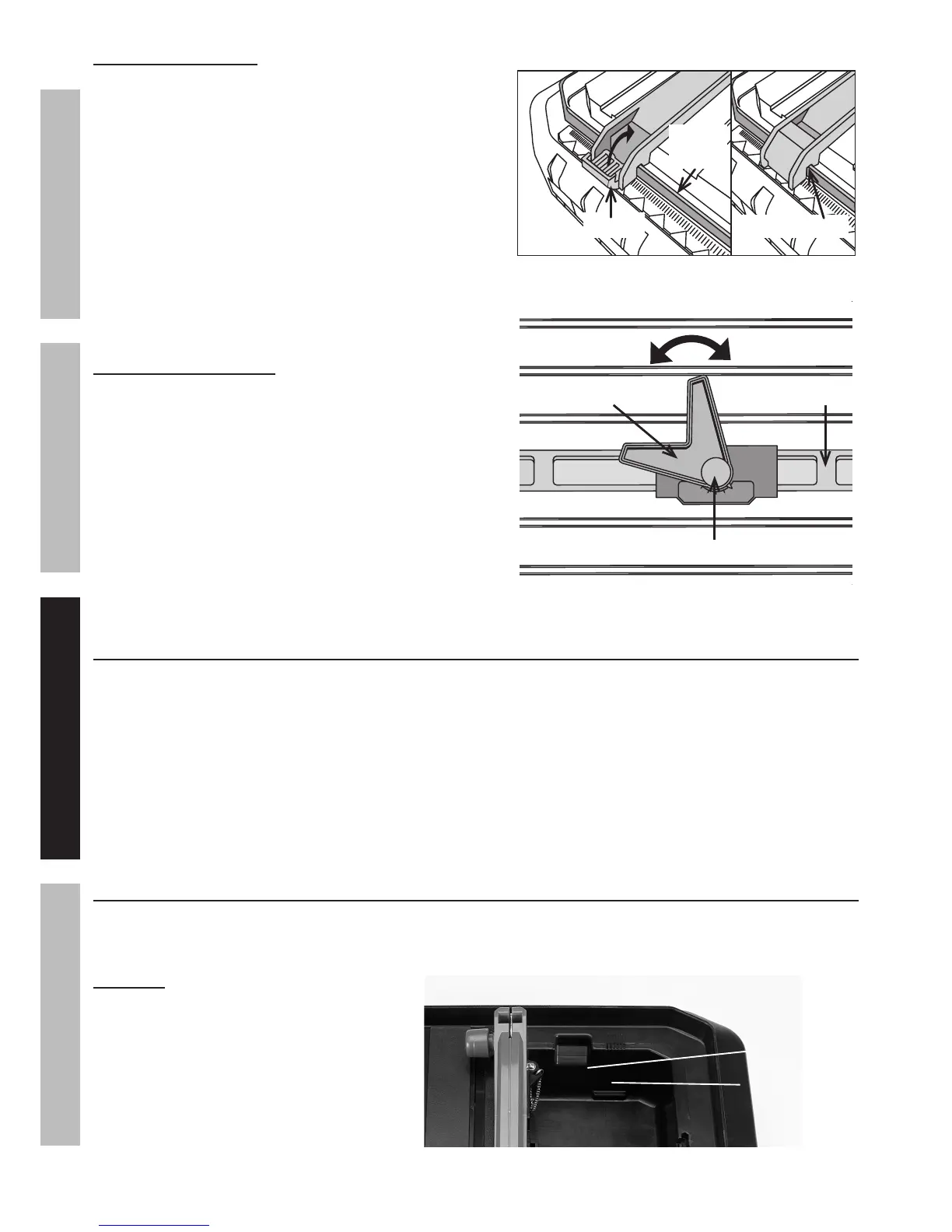
Installing the Rip Fence
1. Pull open the hinges on each end of the Rip Fence and
fit the Rip Fence slots on the Table Top rim.
2. Close the hinges to lock the Rip Fence in place.
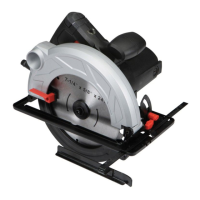
Adjusting the Miter Gauge
1. Place the Miter Gauge assembly on top of the Rip Fence.
2. Loosen the Miter Gauge Knob counterclockwise,
then rotate the gauge to the desired setting.
3. Tighten the Miter Gauge Knob clockwise.
Work Piece and Work Area Set Up
1. Designate a work area that is clean and well-lit.
The work area must not allow access by children
or pets to prevent distraction and injury.
2. Route the power cord along a safe route to reach
the work area without creating a tripping hazard
or exposing the power cord to possible damage.
The power cord must reach the work area with
enough extra length to allow for a drip loop.
3. Make sure that the Base is on a steady level
work surface so the water level of the tank can
be accurately measured and maintained.
4. There must not be objects, such as utility lines,
nearby that will present a hazard while working.
5. Keep workpieces pressed firmly against
the Table and Fence while cutting.
6. Mark cut lines using waterproof marker or crayon.
General Operating Instructions
1. Install the Blade and Upper and Lower Blade Guards.
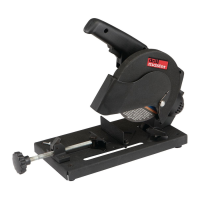
2. Fill the Water Tank to the Maximum fill line marked on the inside of the tank.
CAUTION: Do not operate the
Tile Saw with too little or too much
water in the Water Tank. Keep the
water level between the minimum
and maximum level markings on
the inside of the Water Tank.
Figure 9
Hinge
Table
Top Rim
Rip Fence Slot
Figure 10
Miter Gauge Knob
Miter Gauge Assembly Rip Fence
Figure 11
Maximum fill line
Minimum fill line