3
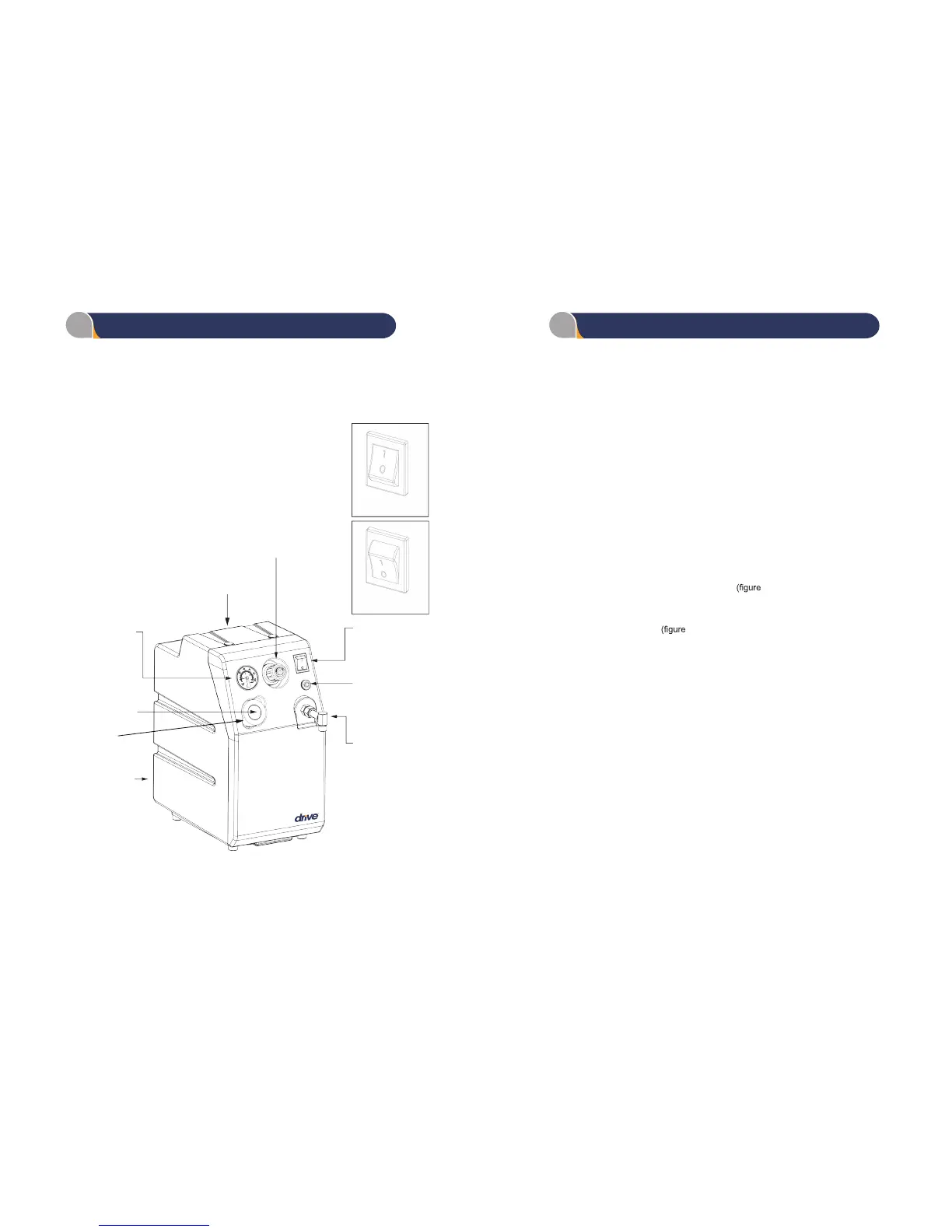
PRESSURE GAUGE
(Indicates pressure)
INTAKE FILTER CAP
INTAKE FILTER
POWER CORD
HANDLE
REGULATOR
(Determines
Pressure output)
ON/OFF SWITCH
(Starts and stops unit)
POWER RESET
(Restarts unit after
overload)
OUTLET PORT
“On” position
“Off” position
FIGURE 1
Replacement Items
18450-ADAPTER
18450-CAP
18450-FILTER
18450-RF
OUTLET PORT
INTAKE FILTER CAP
INTAKE FILTER
REAR CABINENT FILTER
4
INITIAL POSITIONING AND INSTALLATION
OPERATION
1. Select a suitable location for the unit near a 120 VAC, 15 Ampere,
grounded power outlet.
2. Grasp handle on top of cabinet and position the unit so that operating
controls are Accessible to the user and back of unit is away from wall.
3. Make certain that the power switch located in the center of the control
panel is in the OFF position (Figure 1) and plug power cord into grounded
power outlet or grounded adapter.
4. Be certain that all connections to outlet ( i.e. tubing , nebulizers , etc.) are
snug and not leaking aerosol.
5. When used in conjunction with mist tents, etc., place unit outside of tent
and place unit at a level below discharge end of the delivery tubing.
1. Press Power On/Off switch to ON position
1).
ledoM lacideM evirD eht htiw esu ot dnetni uoy tnempiuqe eht tcennoC .2
18450 compressor and then adjust the pressure that the unit is delivering by
adjusting the regulator
1) as follows:
a. Pull regulator knob out to unlock adjustment.
b. Turn dial of regulator to desired pressure.
- clockwise – increase pressure
- counter clockwise – decrease pressure
c. Push knob towards unit locking regulator pressure.
Observe the pressure gauge and adjust regulator up or down to desired
output pressure.
BASIC OPERATING COMPONENTS OPERATING INSTRUCTIONS