Connect the push-in air inlet using the Ø 6 mm nylon line both for the pump and for the mixing component and provide a
shut-off valve that allows interruption of the supply.
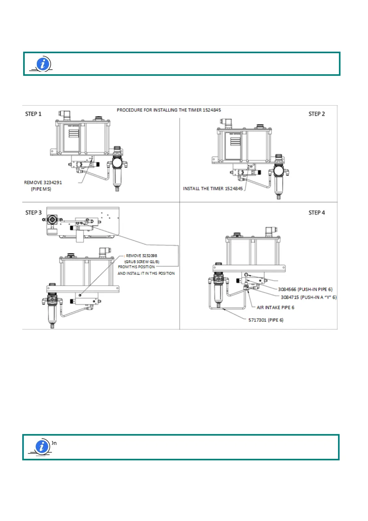
To install the timer, follow the procedure below:
6.7 ELECTRICAL CONNECTIONS
The only electrical connection that must be made is the Samba level connection. (see section 4 technical data)
The Vip4Tools/Air with fixed flow rate pump comes with an inductive proximity sensor (PNP NO 10-30Vdc) to check for
successful oil delivery.
• Temperature limits: - 25 ~ + 70 °C
• 24V absorption: <18mA
• Maximum current output: 200mA
• Operating voltage: 10 ~ 30 Vdc
6.8. CONNECTIONS DIAGRAM
Note: For the fixed flow rate pump version that is available, use Ø 4 mm pipes
Note: Once all the connections have been made, ensure that the pipes and cables are protected from any impact and
that they have been appropriately secured.