Do you have a question about the DROPSA VIP4 Tools and is the answer not in the manual?
Central unit components including reservoir, mixing air system, sub-base, level sensor, and pumps.
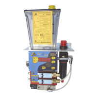
Central unit with solenoid valve, comprising reservoir, sub-base, sensor, pumps, and solenoid valve.
Unit with separate air inlets for independent mini-pump and mixing air control.
Instructions for opening packing, removing equipment, and checking for transport damage.
Guidelines for installation space, height, environment, and mounting bracket use.
Process for assembling mini-pumps onto mixing bases using screws and O-rings.
Steps to insert a new mixing element, including reservoir emptying and fitting connection.
Specifies pump connections using Ø 4 mm nylon piping with push-in fittings.
Describes connecting air inlet using Ø 6 mm nylon line and a shut-off valve.
Details Samba level connection and inductive proximity sensor specifications.
Refers to diagrams illustrating system connections.
Preliminary checks before use, including integrity, connections, and air bleeding.
Instructions on how to bypass lubricant delivery by unscrewing the red cap.
How to adjust nominal pump flow rate using the red cap and turns.
Information on adjusting the timer for mini-pump operating cycles.
Lists available versions and components for the VIP4TOOLS central unit.
Lists available versions and components for the central unit with solenoid valve.
Lists available versions and components for the central unit with fixed flow rate pumps and sensor.
Lists available versions and components for the central unit with separate controls.
Provides dimensions and weights for the VIP 1-litre unit based on the number of elements.
Provides dimensions and weights for the VIP 3-litre unit based on the number of elements.
Provides dimensions and weights for the VIP 3-litre unit with separate controls.
Details the required air quality parameters for system operation.
| Brand | DROPSA |
|---|---|
| Model | VIP4 Tools |
| Category | Lubrication systems |
| Language | English |