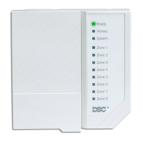
PC1404
Wiring Trikdis GT+ Cellular Communicator and
Programming the Panel
DSC PC1404 panel do not need to be programmed.
trikdis.com
Indicator Light status
NETWORK
O No connection to cellular network
Yellow blinking Connecting to cellular network
Green solid with yellow blinking Communicator is connected to cellular network.
Yellow blinks count indicates signal strength, 10 blinks
max. Suicient cellular signal strength for 4G network -
level 3 (three yellow flashes).
O No unsent events
Green solid Unsent events are stored in buer
Green blinking (Configuration mode) Data is being transferred to/from
communicator
O Power supply is o or disconnected
Green solid Power supply is on with suicient voltage
Yellow solid Power supply voltage is insuicient (≤11.5V)
Green solid and yellow blinking Configuration mode) Communicator is ready for
configuration
Yellow solid (Configuration mode) No connection with computer
O No operation problems
1 red blink SIM card not found
2 red blinks SIM card PIN code problem (incorrect PIN code)
3 red blinks Programming problem (No APN)
4 red blinks Registration to GSM network problem
5 red blinks Registration to GPRS/UMTS network problem
6 red blinks No connection with the receiver
7 red blinks Lost connection with control panel
8 red blinks The entered ICCID number does not match the ICCID
number of the SIM card
Red blinking (Configuration mode) Memory fault
Red solid (Configuration mode) Firmware is corrupted
1 green blink None
2 green blinks GSM
3 green blinks GPRS
4 green blinks EDGE
5 green blinks HSDPA, HSUPA, HSPA+, WCDMA
6 green blinks LTE TDD, LTE FDD
LED indication of communicator operation