29
HOOK-UP DIAGRAM
+
Battery Charge Current:
360mA Max
16V
AC
40VA minimum
12V 4Ah
SEALED
BATTERY
AC POWER
300 mA MAX
TO AUX+
TERMINAL
SIREN
12V
DC
1A maximum
OBSERVE
POLARITY
NC
NO
NC
NC
5600Ω 0.5W
END OF LINE
RESISTOR
LOOP USING
NO and NC
DEVICES
5600Ω 0.5W
END OF LINE
RESISTOR
LOOP USING
NC DEVICES
ONLY
To
PGM
To
AUX
+
Smoke
Detector
Power 12V
DC
IN
OUT
N.O.
ALM
-
OUT
+
-
IN
+
BLK WHT
RED GRN
Latching 4-wire
smoke detector
(ESL model 445C)
5600Ω 0.5W
END OF LINE
RESISTOR
Refer to installation guidelines
when locating smoke detectors.
Alarm initiating
loop resistance:
100 ohms
RM-1 Power loop
supervisory relay
12VDC 35mA max.
GRY BRN RED GRN
RJ31-X CORD
RJ31-X
TELEPHONE
PLUG
WHT
Battery capacity for
emergency standby is at
least 4 hours if the total
load (BELL + AUX O/P) is
800mA or less.
Recommended battery is
Yuasa MNP4-12.
Do not connect transformer to a
receptacle controlled by a
switch.
Temperature Range: 0˚C-47˚C (32˚F-120˚F)
Maximum Humidity: 85% R.H.
BATT 5A
BELL 5A
AUX 1A
WARNING
For continued protection
against the risk of fire,
replace only with the same
type and rating of fuse.
INCORRECT CONNECTIONS MAY RESULT IN
FUSE FAILURE OR IMPROPER OPERATION.
INSPECT WIRING AND ENSURE CONNECTIONS
ARE CORRECT BEFORE APPLYING POWER.
AC
BELL
PGM
OUT
+
-
+
-
YEL
GRN
Z1
COM COM COM
AUX
KEYPAD
Z2 Z3 Z4 Z5 Z6 R-1 T-1
RNG
TIP
LOAD
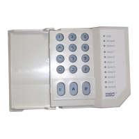
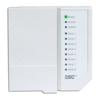
PC1500RK / PC1500RKF
KEYPAD - 5 MAXIMUM
Zone 1
Zone 2
Zone 3
Zone 4
Zone 5
Zone 6
Bypass
Trouble
Armed
Memory
Ready
Refer to Installation Manual
text for detailed instructions
on keypad wiring.
YEL
GRN
RED
BLK