5
Wiring
NOTE: Complete all wiring to the control panel before applying battery or AC power.
If the neutral in the main supply is not readily identifiable, then an appropriate disconnect device that has
a contact separation of at least 3mm and disconnects both poles simultaneously, must be used.
In order to comply with safety requirement IEC950, ensure that when the mains cabling enters the alarm
panel, it is securely clamped to prevent it from being removed.
Interconnection circuits should be such that the equipment continues to comply with the requirements of
IEC950 when like circuits are connected to each other. For example, TNV (telephone network) circuit should
be connected to the TNV circuit, SELV (zoned) circuits should be connected to SELV.
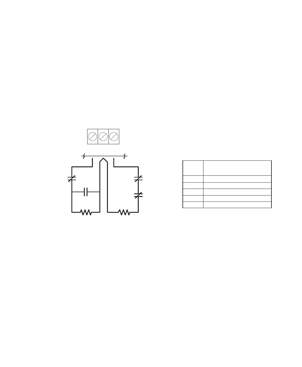
Burglary Zone Wiring
Burglary zone definition, (for example, Delay, Instant, 24-Hour, and so on) is programmed using the keypad.
Refer to Programming Guide Section [01].
Z1
COM Z2
NC
NO
NC
NC
END OF LINE
RESISTOR
5600Ω 0.5W
END OF LINE
RESISTOR
5600Ω 0.5W
EOL RESISTOR
LOOPS USING
NO & NC
DEVICES
EOL RESISTOR
LOOPS USING
NC DEVICES
ONLY
Wire
Gauge
1900 / 579
3000 / 914
4900 / 1493
6200 / 1889
7800 / 2377
24
22
20
19
18
Maximum wire length to
End of Line Resistor
(feet/meters)
Figures are based on maximum wiring
resistance of 100 ohms.
Burglary Zone Wiring Chart
Auxiliary Power Connection
The Auxiliary Power Supply can be used to power keypads, motion detectors and other devices that require
12 VDC. The total load for the Auxiliary Power Supply must be calculated for all devices connected across the
AUX +/- terminals and for devices connected between the AUX + and PGM terminals. The output current cannot
exceed 800 mA when using a 40VA transformer.
PGM Terminal Connections
The PGM terminal is a normally open output that will switch to ground when activated. This output can be
controlled by various programming options; refer to Programming Guide Section [04]. Devices controlled by
the PGM output must be connected between the PGM terminal and the AUX+ terminal.
STR Terminal Connection
The STR (strobe output) terminal is a normally open output that will switch to ground when activated. This output
activates on alarm and remains activated until the system is disarmed. Devices controlled by this output must
be connected between STR and the AUX+ terminal.