Do you have a question about the DSE DSE6120 MKII and is the answer not in the manual?
Describes the wiring connections for various module functions.
Provides a typical system wiring diagram for installation.
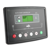
Explains the function of each push-button on the module.
Describes how ECU alarms and Diagnostic Trouble Codes are shown.
Explains how alarms are displayed and managed.
Details non-critical alarm conditions.
Details critical electrical trip alarms.
Details critical shutdown alarms.
Describes the over current alarm and its settings.
How to access and use the main configuration editor.
Recommended checks before starting the system.
Troubleshooting steps for starting problems.
Troubleshooting steps for various alarm conditions.
| Model | DSE6120 MKII |
|---|---|
| Type | Auto Start Control Module |
| DC Supply | 8 V to 35 V Continuous |
| Magnetic Input Frequency | 10, 000 Hz (max) |
| Storage Temperature Range | -40°C to +85°C |
| Relative Humidity | 95% non-condensing |
| Protocol Support | Modbus RTU |
| Digital Inputs | 6 |
| Analog Inputs | 3 |
| Cranking Dropouts | Able to survive 0 V for 50 mS, providing supply was at least 10 V before dropout and supply recovers to 5 V. This is achieved without the need for internal batteries. |
| Enclosure Protection | IP65 (front of module when installed into the control panel) |
| Communication Interface | RS485 |
| Display | LCD |
| Communication | RS485 |