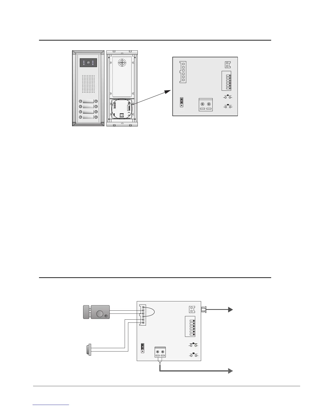
Connect PC
1
2
3
Terminal Descriptions
1 2 3 4 5 6
ON
L1
+12V
T/R -
T/R+
LK - (GND)
CN-LK JP-LK
RS-485
SET
PA
PB
BUS
LK+(COM)
N.O.
EB+
EB -
1
2
3
L2
1 2 3 4 5 6
ON
L1
+12V
T/R -
T/R+
LK - (GND)
CN-LK
RS-485
SET
PA
PB
BUS
LK+(COM)
N.O.
EB+
EB -
1
2
3
L2
DMR11
Connection Board
•
+12V:
12VDC power output.
•
LK-(GND):
power ground.
•
LK+(COM):
electronical load activation relay contact common.
•
NO.:
electronical load activation relay normally open contact (the default setting for this terminal is NO, this
terminal can be configured to NC, normallyclosed contact by the DT CONFIG software). That means, by
default, only the powertounlock type of electronic lock can be connected to the COM and NO terminal, if using
the powerofftounlock type locks, the NO terminal must be set to NC contact by the DT CONFIG software.
•
EB+:
Exit button.
•
EB-:
Exit buton.
•
JP-LK:
For electronic lock safety type setting(refer to Door Station Lock Connections).
•
T/R-:
USBRS485 communication terminal negative.
•
T/R+:
USBRS485 communication terminal positive.
•
SET:
DIP switches for system congurations.
•
PA:
Press once to sent the name list to Monitor; press and hold for 3 seconds to add Master card.
•
PB:
Press once to search the Right line Monitor; press and hold for 3 seconds to search left line Monitor.
•
Bus(
L1,L2
):
nonpolarity bus line.