25
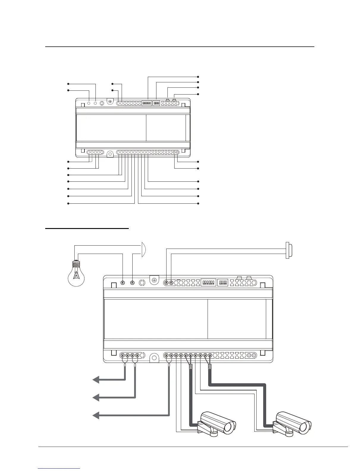
Terminal Connections
1 2 3 4 5 6
ON
1 2 3 4
ON
DCU
LED 2
LED 1
P1
DIP1
DIP2
P2
BUS-IN
BUS-OUT
BUS-DS
+12
GND
VG
VD
+12
GND
VG
VD
COM
NC
EB+
EB-
•
COM:
Contact relay Common terminal
•
NC:
Contact relay Common terminal
•
EB+, EB-:
Contact activate button
•
DIP1:
Main DIP switches
•
DIP2:
Switches for Lock/Light control
•
P1, P2:
Contact relay Common terminal
•
BUS-IN:
Connect to Door Station
•
BUS-OUT:
Connect to Monitors
•
BUS-DS:
Connect to Door Station
•
LED1, LED2:
Indecators
•
+12:
Power+ for CCTV camera
•
GND:
Power for CCTV camera
•
VG:
Video Ground for CCTV camera
•
VD:
Video Core for CCTV camera
1 2 3 4 5 6
ON
1 2 3 4
ON
Connect to
Monitor/Distributor
Connect to
DPS
Connect to
Door Station
AC
DCU
DCU Unit
The DCU unit is a Multi function device which can connect 2 CCVT cameras and light/lock control.



 To Next Page