6. Slowdown (Dipswitch 6)
With dipswitch selected ON, the gate will have a long close and open controlled slow down
distance of 800mm and with the dipswitch OFF, the close and open controlled slow down
distance will remain the same unless programmed to a shorter distance.
(Contact the supplier for instructions to this programming).
NOTE – (Long controlled slow down distance is recommended if the limit is continuously
being overrun).
7. Tamper Alarm Facility (Only available from Version 1.8 software and later)
If the courtesy light feature is not used then the courtesy light relay can be re-configured as
a general Tamper alarm output. Re-configuration is achieved with the following procedure.
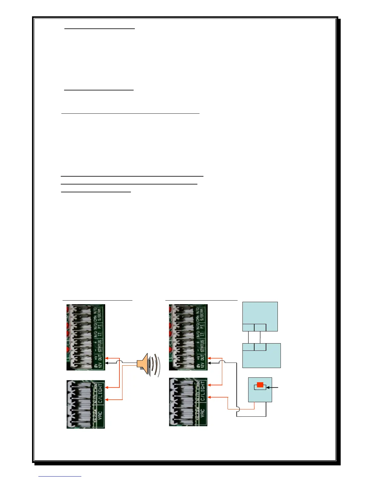
A) Latching tamper (Siren – N/O relay contact) output.
Make note of the option dip switch settings, then remove the power (AC and DC) from the
control PCB and open the gearbox release. Switch all dip switches to the OFF position, then
select dipswitch 1 and 6 to the ON position. Reconnect the power to the PCB and after
approximately 2 seconds, select dipswitch 1 and 6 back to OFF position.
The setting is confirmed by 1 to 5 beeps (depending on where the load pot setting is).
Select the dipswitch settings back as per your notes. Close the gearbox release and perform the
normal power up calibration routine.
B) Impulse tamper (Alarm – N/O relay contact) output. Repeat section A) using dipswitch 1 and 5.
C) Normal Courtesy light mode. (No Tamper alarm). Repeat section A) using only dipswitch 1.
D) Continuous alarm output. Repeat section A) using dipswitch 1 and 4.
The tamper alarm will automatically arm itself when the gate is in the closed position and will trigger
the alarm relay if the gate is moved or forced off the closed limit switch without a valid trigger.
If latching mode is configured, the relay will switch every 3 minutes until the alarm is restored.
If impulse mode is configured, the relay will trigger only once.
Any valid gate or pedestrian input trigger will cancel the tamper alarm which will automatically re-
arm once the gate is again in the close position.
The alarm can also be disabled for maintenance by opening the gearbox release and pressing the
remote control push button (confirmed by 3 short beeps). The alarm will remain disabled until the
gearbox release is closed and the gate closed position re-confirmed.
 Loading...