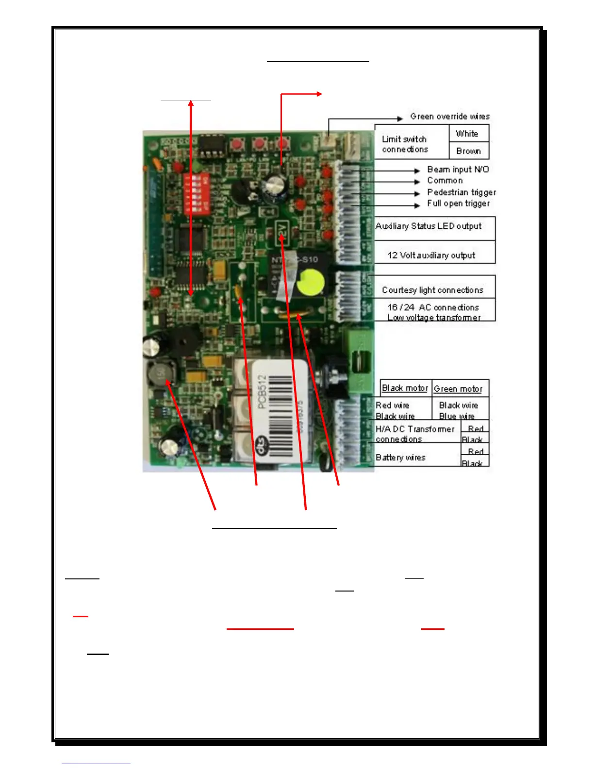
PCB Control card.
AC Jumper Beam option jumper for N/O or N/C beams
500 m/Amp AUX. 2 Amp AC self reset able fuse.
self reset able fuse.
For PCB identification
2 x Voltage regulators = 24V motor. (2
nd
voltage regulator will cover 12V)
1 x Voltage regulator = 12V motor. (New version will have 2 regulators fitted)
NOTE: With the infra red beam option pins not bridged the PCB operates as N/O beams.
. With the option jumper bridged the PCB operates as N/C beams. (Fail safe mode).
NB – When connecting intercoms to the control card (IT and CMN), please ensure that your intercom
trigger output is potential free (ZERO voltage). If not, a gate relay module must be fitted.
Note; 1) The 12V OUT on the 512 PCB’s is an unregulated voltage up to 22Volt DC.
(New 512 version with 2 regulators will have a regulated 12 volt AUX output)
2) The 624 H/A model will have a wire connected from battery positive to the transformer.
3) Please ensure that the auxiliaries connected to the 12 volt auxiliary output does not exceed
500 m/Amps in total. (If so, remove from aux. output and connect directly to battery)