11
CAUTION : To prevent electrical shock or equipment damage, for all units, the Main AC Switch, the Main
DC Switch, all output circuit breakers, and the AC input at the service panel are all off before making AC
connections to the Synchron inverter system.
4. If not previously done, remove knockouts for AC Input and AC Output in the top of the Synchron inverter system
(See Figure 1 in Section 104.1).
CAUTION: Donotdrillthecabinet;drilllingsmaydamagetheunitandpreventitfromoperating.If
larger knockouts are needed, use a chassis punch to enlarge the appropriate knockout. Do not add
additional or unnecessary knockouts.
5. Install the input and output conduits.
6. Run the AC Input service conductors and AC Output conductors through separate conduits. Synchron inverter
system emergency output circuits shall be installed in dedicated conduit systems and not shared with other
electrical circuits as described in NEC 700-9(b).
106.2 AC Input and AC Output Connections
Make all AC input and output connections to the Synchron inverter system as indicated on the labels within the
cabinet. If system was supplied with internal output circuit breaker distribution option, make output wiring connections
directly to the circuit breakers.
107. Final Installation Checklist
Important: Before proceeding to the System Start-Up Procedure (Section 108) complete the Final
Installation Checklist below.
1. Insure the Synchron Inverter cabinet is securely fastened to a wall or other structure.
2. Insure that the input circuit breaker in the building service panel serving as the AC disconnect to the Synchron
system is in the OFF position.
3. Check for proper ground connections in the Synchron Inverter cabinet, the building service panel, and the external
load distribution panel.
4. Check for any loose wiring connections in the Synchron Inverter cabinet, the building service panel, and the
external load distribution panel.
5. Check that correct nominal battery voltage (36, 72 or 96VDC) is present in the Synchron Inverter cabinet between
the DC Input NEG and POS. Refer to Section 105.2 for proper system DC voltage.
6. On the Synchron Inverter insure that the Pre-charge Switch, the Main DC Switch, and the Main AC Switch are all
in the OFF position.
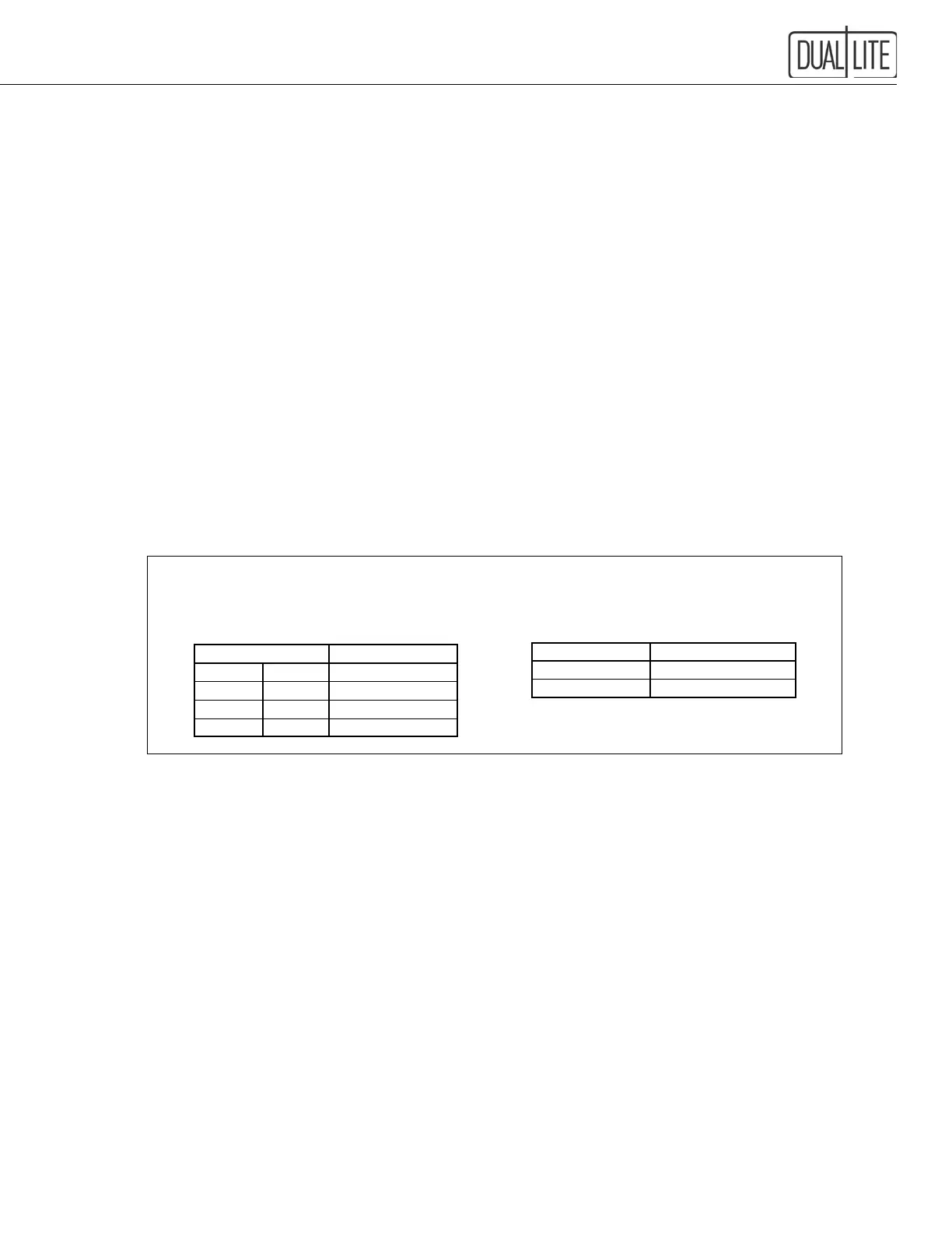
Caution: Torque all connections in accordance with the following tables.
Failuretodosomaycreateanunsafeconditionorrehazard.
"C" Breakers
Rating Torque
amps inch-lbs.
10-30 25
Terminals
Terminal Width Torque
Inches mm inch-lbs.
31/64 12.2 16
19/32 15.2 32
25/32 20 64