9
105.2 Installation Considerations
This section explains how to install the Synchron system’s batteries, fuses, and cables. A qualied electrician who is
familiar with battery installations and applicable building and electrical codes should install the batteries.
105.3 Battery Installation Procedure
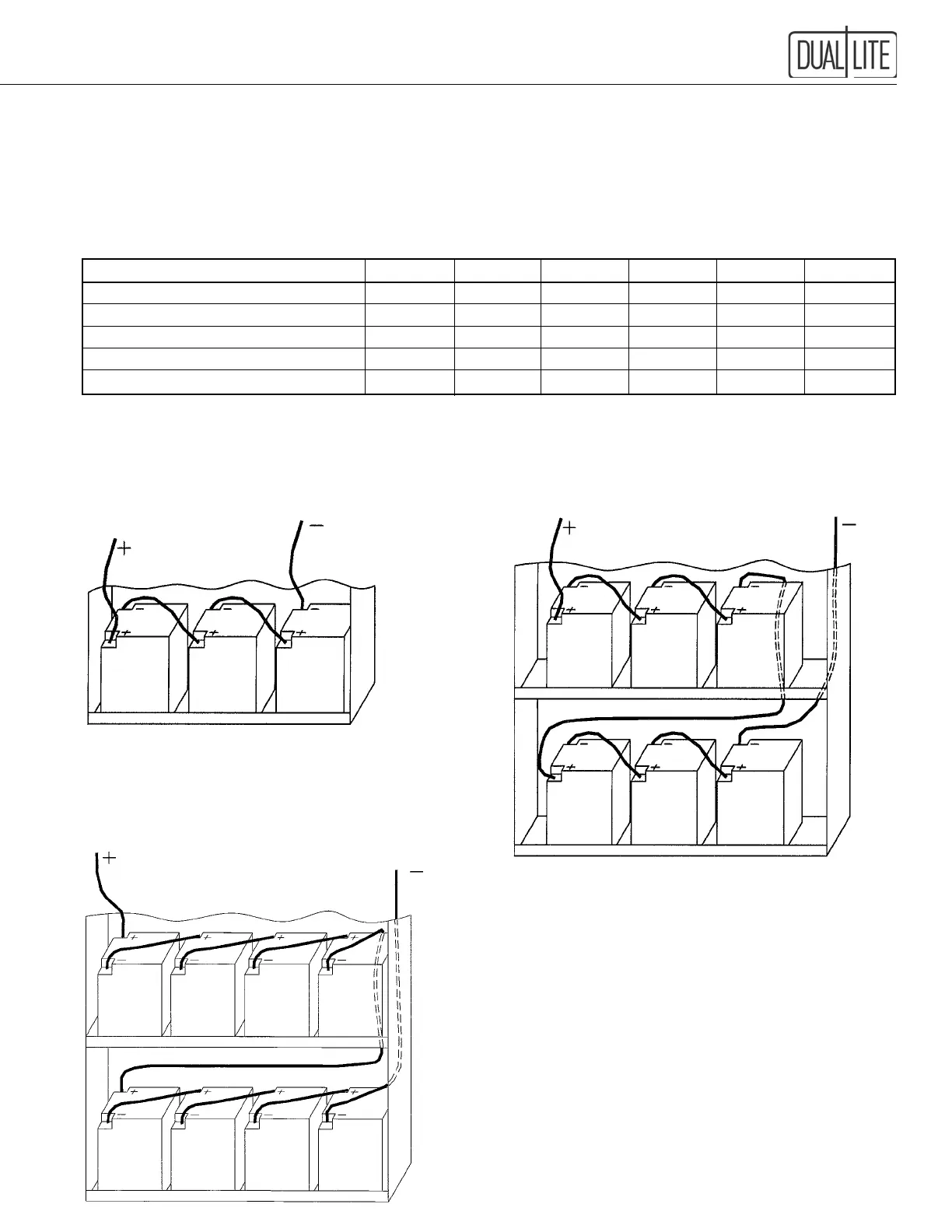
Battery Voltage: Select which wiring diagram to use from this table:
VA/Watts 400 525 750 1000 1500 2100
System DC Voltage 36 36 72 72 72 96
Battery P/N 0120935 0120936 0120937 0120935 93012368 93012368
Number of Batteries 3 3 6 6 6 8
Battery Fuse Rating (Amps) 60 60 60 60 60 60
Wiring Diagram Fig. 1 1 2 2 2 3
IMPORTANT: Be careful to observe correct polarity on the battery terminals. Illustrations are given as a guide only,
polarity markings may vary from battery to battery.
Figure 1 Figure 2
36 Volt Battery Connection Diagram 72 Volt Battery Connection Diagram
400 and 525 VA Model 750, 1000 and 1500 VA Model
Figure 3
96 Volt Battery Connection Diagram
2100 VA Model
IMPORTANT
Once batteries have been wired as shown, the system's DC fuse
must be installed.
MAKE SURE THE DC BREAKER IS IN THE OFF
POSITION BEFORE PROCEEDING.
The DC fuse is shipped separately inside the cabinet and needs
to be installed in its fuse block holder located on the underside
of the electronics shelf. Use insulated tools to perform this
task, full battery voltage will be present at the fuse block.
DO NOT TURN ON THE DC BREAKER AT THIS
TIME AS SIGNIFICANT DAMAGE TO THE SYSTEM
WILL OCCUR.
See Section 108 for proper system start-up procedure.