Dear record-lover: Please
read these
instructions
carefully before
you
set up
and
operate
your
new
automatic
turntable.
By
doing so,
you
will avoid faulty operation
or
possible
damage
due to mistakes in
installation.
Move page
2 outward.
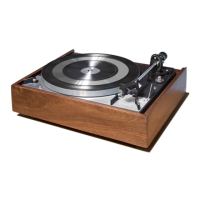
Unpacking
See
the
separate
unpacking instructions.
This
instruction
applies only if
you
have
bought
the Dual 1215
as a separately
packed
component. lnstall
the
platter
by
lowering
it carefully
and slowly onto
the
shaft. An
oil-soaked felt
washer will
be
pushed
out
as
you
lower
the turntable
platter,
thus
oiling
the
shaft.
lt
can then
be discarded.
lf
your
1215
does
not have
a cartridge
installed, you
will
find
installation
instruc-
tions on
page
10.
With
the
tonearm
locked
in
place,
install
the
counterbalance
at the rear
of the
tone-
arm.
You will
find
further
instructions
for
balancing
the
tonearm
and
setting
stylus
force
on
pages
10
and 11
of these
instruc-
tions.
For
the
correct
stylus
force,
which
depends
on the
make
and
model of
cart-
ridge,
follow
the
instructions provided
with
the
cartridge.
Note:
After
initial
installation
and
after
every
transport,
allow
the
automatic
me-
chanism
to
adjust
itself
by operating
the
1215
through
one
change
cycle
with
the
tonearm
locked
on its
rest
(move
the
opera-
ting
lever
to
"start").
lnstallation
The
installatjon
instruction
is
only important
if
the
phonograph
is
bought without
bäse.
'
lf yoursystem
requires
a
preamplifier,
make
the
necessary
connections
to the
Dual
1 21
5.
The
following
instructions
are
exceedingly
simple:
Press
the
chassis
mounting
screws
toward
the
edge
of the
chassis
with your
thumbs
and
set the
chassis
down
on the
base
cut-
out
so that
the
three
spring
cups
slip into
their
holes
(A).
Then
turn
the
mounting
screws
cloctwise.
The
chassis
is
now
spring-mounted (B).
To secure the unit
for transport,
unscrew
the mounting screws,
pull
them
up, then
turn them further until
the chassis
is
se-
cured tightly to
the
mounting board
(C).
To
prepare
the unit for use again,
turn the
two
screws clockwise
until
they
slide down
about 3/4", then continue to turn in the
same direction until they
are
tight.
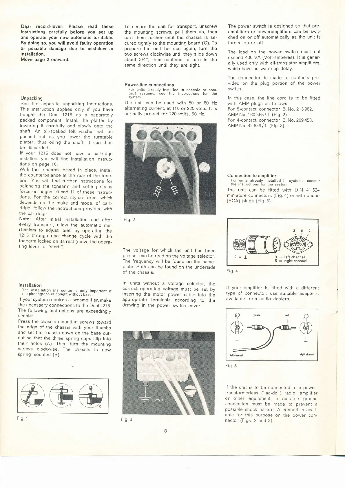
Power-line
connections
For
units already installed
in concole
or com-
pact
systems,
see the
instructions for
thq
system.
The
unit can
be used with 50 or
60 Hz
alternating
current, at 1 1
0 or 220 volts. lt
is
normally
pre-set
for
220 volts,
50 Hz.
The
voltage for
which
the unit has
been
pre-set
can be read
on the voltage
selector.
The frequency
will
be
found
on the name-
plate.
Both
can
be found
on the
underside
of the
chassis.
ln
units
without
a voltage
selector,
the
correct
operating
voltage
must
be
set
by
inserting
the motor power
cable
into
the
appropriate
terminals
according
to
the
drawing
in
the
power
switch
cover.
The
power
switch
is designed
so
that
pre-
amplifiers
or
poweramplifiers
can
be swit-
ched on
or off automatically
as
the unit is
turned on or off.
The load on the
power
switch
must not
exceed 400
VA
(Volt-amperes).
It is
gener-
ally used only
with
all-transistor
amplifiers,
which have no warm-up delay.
The connection is made to contacts
pro-
vided
on the
plug portion
of
the
power
switch.
ln
this case, the line cord is
to
be
fitted
wjth AMP
plugs
as follows:
For 5-contact
connector
B.
No.2'13982,
.AMP
No. 1
60 56s
/
1
(Fig.
2)
For 4-contact connector B.No. 209458,
AMP No. 42859
l1
(Fig.
3)
Connection to amplifier
For
units already installed
in systems,
consult
the instructions
for
the system.
The
unit can be fitted
with
DIN
41
524
miniature
connectors
(Fig.
4)
or
with
phono
(RCA) plugs (Fig.
s).
2:
L
3
=
leftchannel
5
:
right
channel
lf
your
amplifier is fitted with
a different
type
of connector,
use sultable adapters,
available
from
audio dealers.
lf the
unjt is to
be connected to
a
power-
transformerless ("ac-dc")
radio, amplifier
or
other equipment,
a suitable
ground
connection
must
be made
to
prevent
a
possible
shock
hazard.
A
contact
is
avail-
able for
this
purpose
on the
power
con-
nector
(Figs.
2 and
3).
l
l
I
Fig
I
l
I
Frg
@@@
Fig. I
Fig. 2
a
16)
\ti7
i
t
Fig. 3
 Loading...