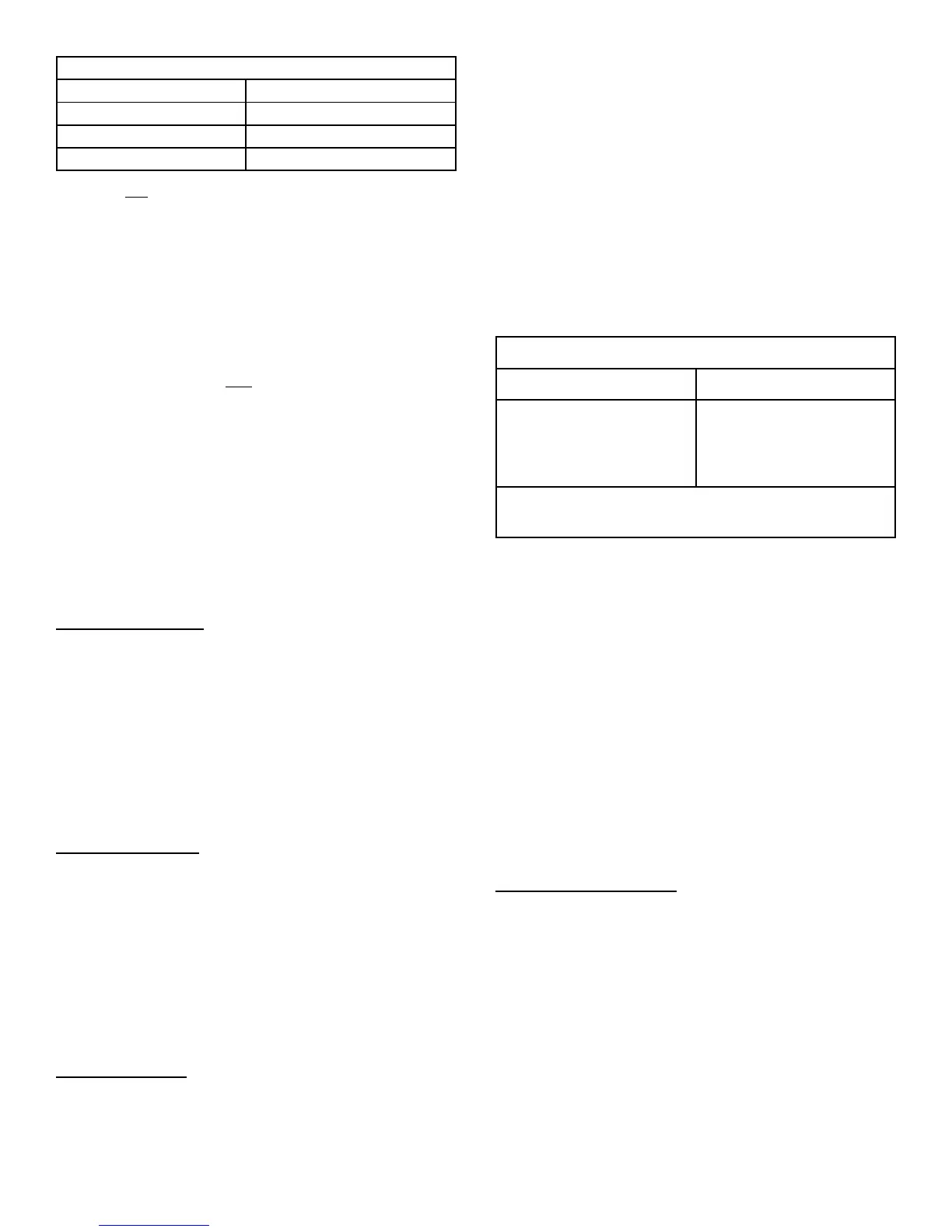
Table 2 - Control Wiring Size
For length of wire up to: Use minimum wire size of:
30 feet 22 AWG*
100 feet 20 AWG
150 feet 18 AWG
* Use only high quality 22 AWG wire
Ensure room thermostat is properly installed per
instructions shipped with room thermostat. Generally,
thermostat should not be exposed to sunlight, drafts or
vibration and should not be mounted on exterior walls.
Low voltage control wire connections should be made as
noted on the wiring diagram on the inside cover of the
outdoor unit. Generally, the connections from room
thermostat to indoor unit and indoor unit to outdoor unit are
connected point to point (Y to Y, C to C, etc.), with points
as follows:
"Y" (compressor) - yellow
"C" (common) - black or brown
"G" (indoor fan) - green
"R" (24 Vac) - red
"O" (reversing valve) - orange (heat pump only)
"W" (first stage heat) - white (furnace only)
"W1" / "W2" (supplemental heat) - white (heat pump only)
Pre-Start Procedure
1. Check to ensure:
• service valve caps are installed and tightened
• voltage supply at unit agrees with nameplate rating
• all factory and field wiring connections are tight
• indoor fan motor is on correct speed tap
2. Close electrical disconnects to energize system.
3. Energize crankcase heater, on units so equipped, for
8 hours before operating the units.
Start-Up Procedure
1. Set thermostat selector switch to OFF.
2. Set room thermostat at desired temperature. Be sure
set point is below indoor ambient temperature.
3. Set the system switch of the thermostat on COOL and
fan switch for continuous operation or AUTO, as
desired. Operate unit for 15-20 minutes, then check
the system refrigerant charge.
4. Adjust refrigerant charge per "Adjusting Charge"
section.
Adjusting Charge
All split system units are factory charged for 15 feet of
connecting line set and matched evaporator coil.
Refrigerant charge should initially be adjusted for line set
lengths other than 15 feet. For line sets shorter than 15
feet in length, remove charge per Table 3. For line sets
longer than 15 feet, add charge per Table 3. Oil charge is
sufficient for all line lengths.
Final charge adjustments must be in the cooling mode by
subcooling / superheat check, only when outdoor ambient
is above 60°F. If the outdoor ambient is below 60°F,
adjust charge only by weight and recheck later when
ambient is above 60°F.
Heat pumps should also have performance checked in
heating mode. The only acceptable method to charge a
heat pump in the heating mode is by weight.
Table 3 — Refrigeration Charge Adjustment
Liquid Line Diameter Oz. Per Linear Foot *
1/4"
5/16"
3/8"
1/2"
.25
.45
.60
1.20
* Factory charge for series is for 15' (ft.) line sets
and evaporator coil.
Before final adjustment is made to the refrigerant charge,
it is imperative proper indoor airflow be established.
Airflow will be higher across a dry coil versus a wet coil.
Blower charts are usually calculated with a dry coil.
Recommended airflow is 350-450 CFM per ton (12,000
Btuh) through a wet coil. Refer to indoor unit instructions
for methods of determining air flow and blower
performance.
With outdoor ambient above 60°F, the refrigerant charge
should be adjusted first by weight, then final adjustment by
super heat (for piston systems) or subcool (for TXV
systems).
Piston System Charging
1. Operate unit for minimum of 10 minutes.
2. Measure pressure and temperature at vapor valve
service port. Use a good thermistor or electronic
thermometer.
3. Subtract saturation temperature (of measured
pressure) from temperature measured to obtain
superheat. Refer to Table 4 for saturation
temperatures of R-22.
4. Measure outdoor dry bulb using a good thermometer
and indoor wet bulb using a sling psychrometer.
5. Using measured temperatures, find closest outdoor dry
bulb and indoor wet bulb temperatures in the chart
inside control cover and locate required superheat.
20407502 ISSUE 0144 Page 5 of 8