1. In seriesflow applications, the coil is mounted after the
furnace in an enclosure in the supply air stream. The furnace
blower is used for both heating and cooling airflow.
2. In parallel flow installation, dampers must be provided to
direct air over the furnace heat exchanger when heat is desired
and over the cooling when cooling is desired.
IMPORTANT: The dampers should be adequate to prevent
cooled air from entering the furnace, and if
manually operated, must be equipped with
means to prevent operation of either the cooling
unit or furnace unless the damper is in the full
cool or full heat position.
WARNING
The coil MUST be installed on the air discharge
side of the furnace. Under no circumstances should
the air flow be such that cooled, conditioned air can
pass over the furnace heat exchanger. This will
cause condensation in the heat exchanger and
possible failure ,of the heat exchanger that could
lead to a fire hazard and/or hazardous conditions
that may lead to bodily harm. Heat exchanger
failure due to improper installation may not be
covered by warranty.
Gas piping shall be of such size and so installed as to provide
a supply of gas sufficient to meet maximum demands without
undue loss of pressure between the gas meter and the furnace. It is
recommended that the gas line to the furnace shall be a separate
line direct from the meter, unless the existing gas line is of ample
capacity. Refer to gas pipe capacity table in the National Fuel Gas
Code (ANSI 7-,223.1)or the CANI-B 149 Installation Code.
Use ajoint compound (pipe dope) that is resistant to the action
of liquefied petroleum gases or any other chemical constituents of
the gases to be conducted through the piping.
NOTE: In order to make proper input adjustments, minimum and
maximum gas supply pressure limits shown on the rating
plate must not be exceeded.
Before any system of gas piping is finally put into service, it
should be carefully tested to determine if it is gas tight. Check all
piping for leaks using soapy water and a brush. The piping must
stand a pressure of six (6) inches of mercury for a period of ten
(10) minutes or as required by local authority.
WARNING
The furnace and its individual shutoff valve must
be disconnected from the supply piping system
during any pressure testing of that system at test
pressures in excess of 1/2 PSIG (3.5kPa or
14"w.c.).
The furnace must be isolated from the gas supply
piping system by closing its individual manual
shutoff valve during any pressure testing of the
gas supply piping system at pressures equal to or
less than 1/2 PSIG (3.5kPa or 14"w.c.). Failure to
follow the above procedures couId lead to a
hazardous condition and bodily harm. o
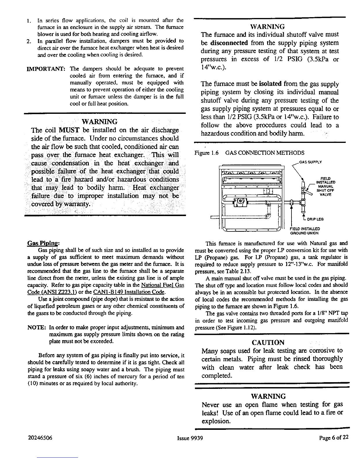
Figure 1.6 GAS CONNECTION METHODS
,_LTS
r• • , • •
FIELD
SHUT OFF
VALVE
l'
I_ DRIP tea
FIELD INSTALLED
GROUND UNION
This furnace is manufactured for use with Natural gas and
must be converted using the proper LP conversion kit for use with
LP (Propane) gas. For LP (Propane) gas, a tank regulator is
required to reduce supply pressure to 12"-13"w.c. For manifold
pressure, see Table 2.13.
A main manual shut off valve must be used in the gas piping.
The shut off type and location must follow local codes and should
always be in an accessible but protected location. In the absence
of local codes the _conm_nded methods for installing the gas
piping to the furnace are shown in Figure 1.6.
The gas valve contains two threaded ports for a 1/8" NPT tap
in order to test incoming gas pressure and outgoing manifold
pressure (See Figure 1.12).
CAUTION
Many soaps used for leak testing are Corrosive to
certain metals. Piping must be rinsed thoroughly
with clean water after leak check has been
completed.
WARNING
Never use an open flame when testing for gas
leaks! Use of an open flame could lead to a fire or
explosion.
20246506 Issue 9939 Page 6 of 22
 Loading...