FAectrical:
The control system depends on the correct polarity of the
power supply. Connect "hot" wire (H) and "ground" wire "G'"' as
shown in Figures 1.21 & 1.22. Reference table 1.20 for furnace
over current protection, current rating and wire size. Use copper
wire only for ll5V-supply service to unit. When replacing any
original internal wiring, use only 105°C, 16 AWG copper wire.
Instructions for wiring the thermostat are packed in the
thermostat (field supplied) box. Make the thermostat connections
as shown in Figures 1.21 & 1.22 at the 24-volt terminal board
located in the control box.
When installing optional accessories to this appliance, follow
the manufacturer's installation instructions included with the
accessory. Other than wiring for the thermostat, a minimum of
type T (63°F rise) must be used.
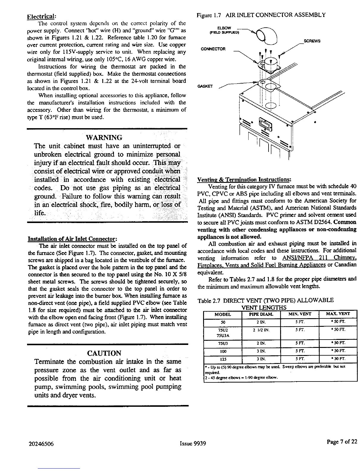
Figure 1.7 AIR INLET CONNECTOR ASSEMBLY
CONNE_OR
GASKET
WARNING
The unit cabinet must have an uninterrupted or
unbroken electrical ground to minimize personal
injury if an electrical fault should occur. This may
consist of electrical wire or approved conduit when
installed in accordance with existing electrical
codes. Do not use gas piping as an electrical
ground. Failure to follow this warning can result
m an electrical shock, fire, bodily harm. or loss of
life.
Installation of Air Inlet Connector:
The air inlet connector must be installed on the top panel of
the furnace (See Figure 1.7). The connector, gasket, and mounting
screws are shipped in a bag located in the vestibule of the furnace.
The gasket is placed over the hole pattern in the top panel and the
connector is then secured to the top panel using the No. 10 X 5/8
sheet metal screws. The screws should be tightened securely, so
that the gasket seals the connector to the top panel in order to
prevent air leakage into the burner box. When installing furnace as
non-direct vent (one pipe), a field supplied PVC elbow (see Table
1.8 for size required) must be attached to the air inlet connector
with the elbow open end facing front (Figure 1.7). When installing
furnace as direct vent (two pipe), air inlet piping must match vent
pipe in length and configuration.
CAUTION
Terminate the combustion air intake in the same
pressure zone as the vent outlet and as far as
possible from the air conditioning unit or heat
pump, swimming pools, swimming pool pumping
units and dryer vents.
Venting & Termination Instructions:
Venting for this category IV furnace must be with schedule 40
PVC, CPVC or ABS pipe including all elbows and vent terminals.
All pipe and fittings must conform to the American Society for
Testing and Material (ASTM), and American National Standards
Institute (ANSI) Standards. PVC primer and solvent cement used
to secure all PVC joints must conform to ASTM D2564. Common
venting with other condensing appliances or non-condensing
appliance* is not allowed.
All combustion air and exhaust piping must be installed in
accordance with local codes and these instructions. For additional
venting information refer to ANSI/NFPA 211 Chimney,
Fireplaces, Vents and Solid Fuel Bumin_ Anoliances or Canadian
equivalenL
Refer to Tables 2.7 and 1.8 for the proper pipe diameters and
the minimum and maximum allowable vent lengths.
Table 2.7 DIRECT VENT (TWO PIPE) ALLOWABLE
VENT LENGTHS
MODEL PIPEDIAM.
50 2_.
75U2 2 1_.
75U3A
75W 2_.
1_ 3_.
125 3_.
MIN. VENT MAX. VENT
5FT. *:;OFT.
5FT. * 50 FT.
5FT. * 50 FT.
5zr. * 50 F'r.
5FT. *50FT.
*- Up to (5) 90 degree elbows may be used. Sweep elbows are poeretable but not
required.
2 - 45 degree elbows - 1-90 degree elbow.
20246506 Issue 9939 Page 7 of 22
 Loading...