Table 1.8 NON-DIRECT VENT (ONE PIPE) ALLOWABLE
VENT LENGTHS
MODEL INTAKE PIPE DIAM.
ELBOW DIA.
50 2l/q. 2IN.
7502 3 IN. 2 I/2 IN.
7503A
75U3 2 IN. 2 IN.
ICO 3 IN. 3 IN.
125 3IN. 31N.
,%nN. VENT MAX. VENT
5FT. * 50 Ft.
5FT. * 50 FT.
5FT. *50 FT.
5FT. *50FL
5FT. * 50 FT.
"- Up to (5) 90 degree elbows may be used. Sweep elbows ave pntretable but not
requited.
2 - 45 de_,rt e elbows - 1-90 de_'ee elbow.
The following requirements are necessary for a safe venting
system:
1) All pipe should be supported using clamps and/or straps.
These supports should be at least every four (4) feet, or as
required by local codes.
2) All horizontal vent runs must be sloping upwards to obtain
1/4" (in.) rise per foot of pipe from the furnace to the vent
terminal. This insures proper drainage of the condensate back
to the condensate drain. Failure to maintain dfis rise will
cause condensate to accumulate in the pipe,
3) Direct Vent (two pipe) units may have either a 90* elbow or a
straight coupling attached to the air inlet plate. Do not seal
the top joint of the fitting. This joint must be left unglued to
facilitate unit access during any required maintenance.
4) All units regardless of vent configuration must use the
secondary exhaust pipe drain (supplied) as shown in Figures
2.8 and 3.8 or the alternate arrangements as shown in the
vent/drain instmcdous packed in the vent kit in the furnace.
5) Joints in PVC should be sealed with PVC cement and chocked
for leaks. ABS or CPVC venting should use sealant as
specified by the pipe manufacturer.
6) Cheek all local codes for any variance.
NOTE: If 2 I/2" or 3" vent pipe is required, the appropriate
supplied adapter must be used. Install the adapter at the
vent outlet of the vent/drain tee (see instructions in vent
kit).
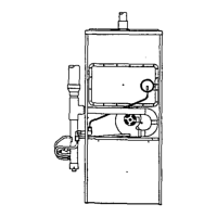
Figure 2.8 UPFLOW VENTING OPTIONS
Figure 3.8 LEFT HORIZONTAL VENTING
12" MINIMUM CLEARANCE
P_EQUIRED
The vent system can be installed through an existing chimney
provided that:
a) No other appliance is vented into the chimney.
b) The termination clearances shown in Figure 4.8 are
maintained.
c) Both the air intake and exhaust vent run the length of the
chimney.
d) The top of the chimney is sealed and weatherproofed.
Vertical Vent Termination:
The vertical vent terminations should be sealed with a
plumbing roof boot or equivalentflashing.
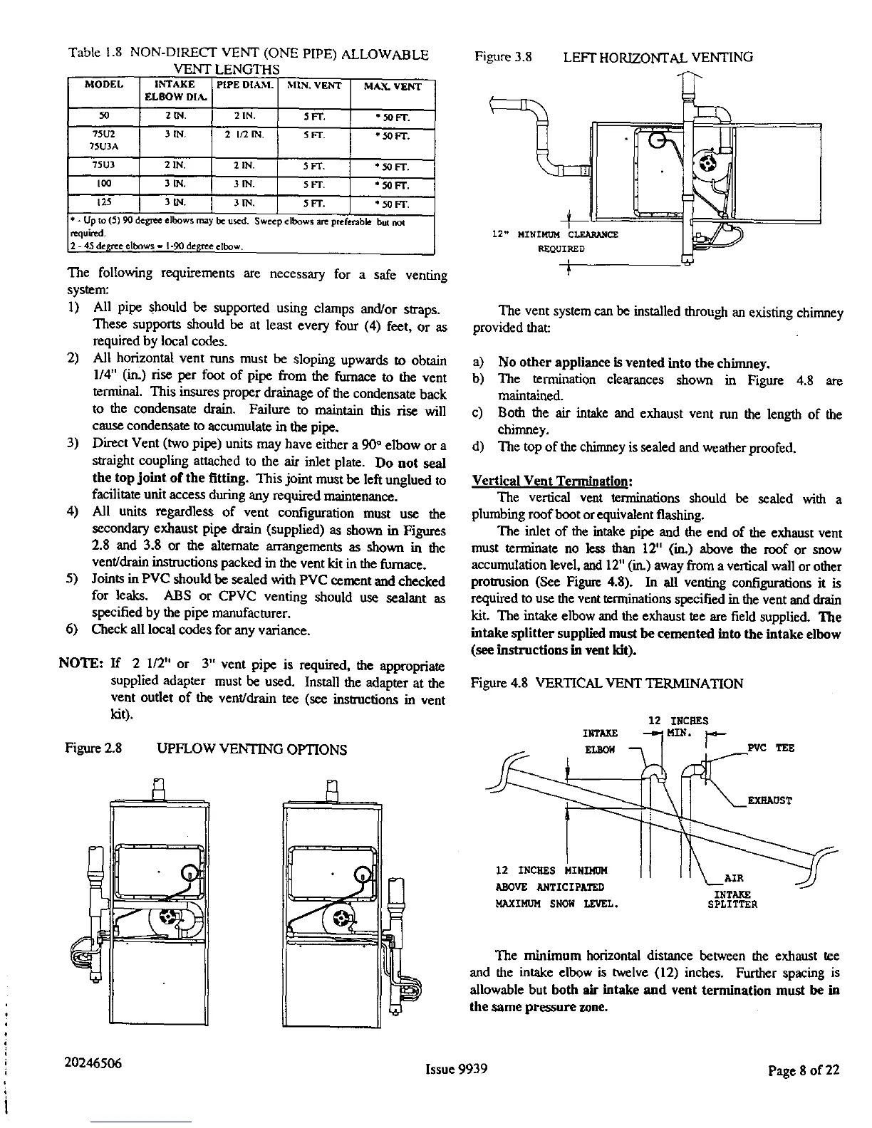
The inlet of the intake pipe and the end of the exhaust vent
must terminate no less than 12" (in.) above the roof or snow
accumulation level, and 12" (in.) away from a vertical wall or other
protrusion (See Figure 4.8). In all venting configurations it is
required to use the vent terminations specified in the vent and drain
kit. The intake elbow and the exhaust tee are field supplied. ']['he
intake splitter supplied must be cemented into the intake elbow
(see instructions in vent kit).
Figure 4.8 VERTICAL VENT TERMINATION
12 INCHES
INTAKE MIN.
EI_ [ PVC TEE
EXHAUST
12 INCHES MINIMOM
ABOVE ANTICIPATED
MAXIMUM SNOW LEVEL.
INTA_
SPLITTER
The minimum horizontal distance between the exhaust tee
and the intake elbow is twelve (12) inches. Further spacing is
allowable but both air intake and vent termination must be in
the same pressure zone.
20246506 Issue 9939 Page 8 of 22
 Loading...