Horizontal (Side Wall) Vent Termination:
To prevent blockage of the combustion air and exhaust vent
by snow, vent termination must be made 12" (in.) above the
anticipated maximum snow accumulation level (See Figure 1.9).
WARNING
Failure to terminate vent runs above the annual
snow accumulation level may result in nuisance
furnace shutdown and/or hazardous condition that
may lead to bodily harm or loss of life.
A minimum of 4' (ft.) clearance must be provided from
electric meters, gas meters, regulators and relief equipment. In
Canada refer to the current CAN/CGA B 149.1 and 2.
Direct vent (two pipe) terminations must terminate not
less that one-foot above, below or horizontal from any inlet to
building.
Non-direct vent (one pipe) termination must terminate at
least 4 feet below, 4 feet horizontally from, or 1 foot above any
inlet to building.
Do not terminate over public walkways or over an area
where condensate or vapor could create a nuisance or hazard. In
Canada refer to the current CAN/CGA B149.1 and 2.
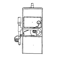
Figure 1.9 HORIZONTAL VENT TERMINATION
HORIZONTALVENTTERMINATION
NOTE: T MIN. CLEARANCE
TO NEAREST BUILDING
OR WALL.
1.5" MIN.
18" MAX._
WALL 12 IN, ,VdN.
IHICKNESS -- _ 12 IN. I_N. i
l I J
i t i i
_FLUE Otm_ET _
COJJPLING _" "" .... _" MIN. !
_AIR INLET
m
TOP VIEW SlOE VIEW
IH£ HORIZONTAL OI_TANCE IIETVCEEN THE INTAKE PIPE AND EXHAUST PIpE CAN 8E
INCRFJtSEO IF N_RY _ THE TERIdl NA'_ON MUST RI_dAIN IN THE
PRESSURE ZONE.
; ,
i i
i
i J
MUST HAVE A 114' SLOPE
"_'JWAAO I_E FURNACE _R
VEto"
Condensate Disposal Drain:
This furnace must use the condensate trap supplied with the
unit (See Figure 2.9) or altemate condensate drain/trap
arrangement (See Figure 3.9) for proper drain installation. The
ahemate arrangement should be used for uptTow installations when
the vent and condensate drain must be on opposite sides of the
furnace or for horizootal installation when space below the unit to
put the drain trap is at a minimum (order alternate condensate
drain/trap kit #20280001). The drain must terminate at a floor
drain, sewer system, or drain vent for proper condensate removal.
Drain installation must conform to local building codes.
NOTE: The condensate trap (supplied) must be connected to the
PVC tee provided on the unit. Failure to place the trap,
as per these instructions, may cause erratic unit operation
and nuisance furnace shutdown.
In addition the trap must be filled with water on the initial
start-up of the unit. installation location may require that the trap
be filled at the beginning of each heating season.
In addition, if this unit is placed in an unconditioned space
such,as an attic or crawlspace where the temperature could be at
freezing or below; a thermostatically controlled beat tape must
be installed along the entire length of condensate drain in the
unconditioned space.
WARNING
Failure to install a heat tape on condensate drain
lines in unconditioned spaces could lead to
nuisance furnace shut-down, water damage,
and/or a hazardous condition which may lead to
bodily harm, or loss of life.
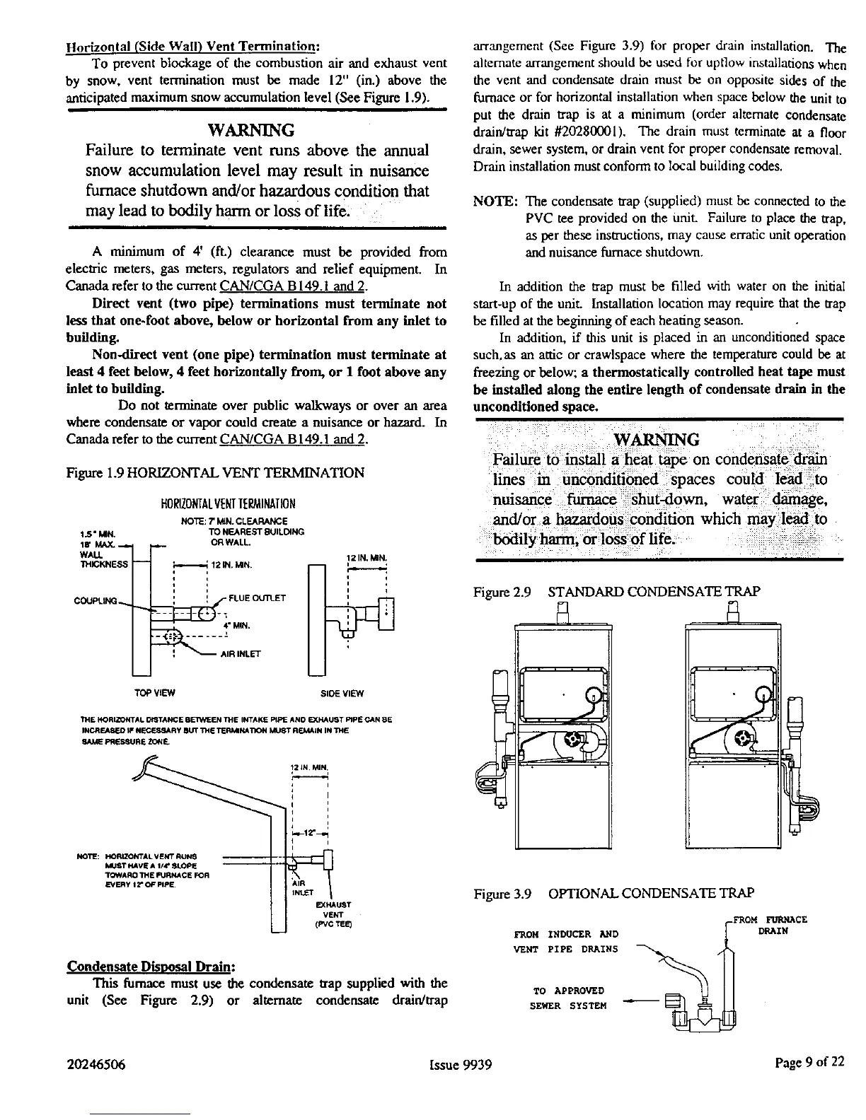
Figure 2.9 STANDARD CONDENSATE TRAP
Figure 3.9 OPTIONAL CONDENSATE TRAP
FROM INDUCER A//D
VENT PIPE DRAIHS
TO APPROVED
SEWER SYSTEM
_FROM FURNACE
DRAIN
20246506 Issue 9939 Page 9 of 22
 Loading...