Cód. ISTR / Cod. ISTR - 581Pag. - Page 10/16
ED./ED. 00
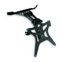
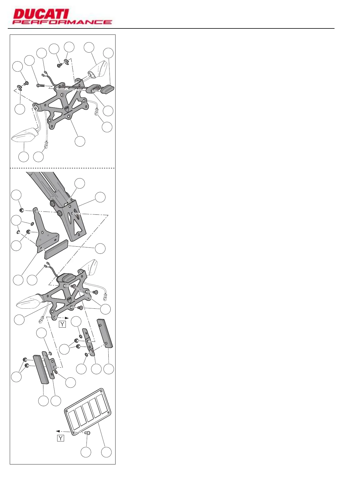
Number plate holder plate
assembly (US version)
Insert wiring (18A) of number plate light (18)
inside spacer (17).
Position spacer (17) and number plate light
(18) on number plate holder plate (33) by
routing wiring (18A) inside the suitable hole
on the number plate holder and start 2
screws (15).
Tighten 2 screws (15) to a torque of 6 Nm ±
10%.
Position the original LH turn indicator (M1)
on the number plate holder plate (33) by
routing wiring (M2) in the suitable slot; on
the opposite side, position plate (12) and fix
the turn indicator (M1) by tightening screw
(13) to a torque of 3 Nm ± 10%.
Repeat the same operation to fix the
original RH turn indicator (N1).
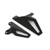
Pre-fit the central cat's eye (24) on plate (23)
and block it with 2 crown rings (11).
Pre-fit 2 lateral cat's eyes (24) on 2 lateral
retaining plates (25) and block them with 4
crown rings (11).
Insert number plate light wiring (18A) inside
slot (5A).
Position the number plate holder unit (33)
on the lower bracket (9) and start 2 screws
(19); on the other side, position the just
fitted central cat's eye unit on the screw
threads and tighten nuts (10) to a torque of
10 Nm ± 10%.
Position the pre-fitted lateral cat's eye units
on the number plate holder plate (33)
internal side by matching the holes and start
2 screws (19) in the upper holes.
Screw 2 nuts (10) on screw (19) threads to
a torque of 10 Nm ± 10%.
Position number plate (V) on the relevant
holder unit (33), start 4 original screws (V1)
and on the internal side screw 4 nuts (10).
12
13
13
12
N1
17
18
15
18A
18A23
33
M1 M2
N2
9
24
24 25
5A
11
10
10
33
19
VV1
2511
11
10
10
24
11
11
Montagem do prato porta-
matrícula (versão US)
Faça a cablagem (18A) da luz da matrícula
(18) correr dentro do espaçador (17).
Posicione no prato porta-matrícula (33) o
espaçador (17) e a luz da matrícula (18),
fazendo a cablagem (18A) passar na
específica perfuração no porta-matrícula e
introduza os n.2 parafusos (15).
Aperte os n.2 parafusos (15) a um binário de
6 Nm ± 10%.
Posicione o indicador de direção esquerdo
original (M1) no prato porta-matrícula (33),
fazendo a cablagem (M2) passar na
específica perfuração; pela parte oposta,
posicione a placa (12) e fixe o indicador (M1)
atarraxando e apertando o parafuso (13) a
um binário de 3 Nm ± 10%.
Repita a mesma operação para fixar o
indicador de direção direito original (N1).
Monte o refletor central (24) na placa (23),
bloqueando-o com os n.2 anéis tipo coroa
(11).
Monte os n.2 refletores laterais (24) nas n.2
placas de fixação laterais (25), bloqueando-
os com os n.4 anéis tipo coroa (11).
Faça a cablagem (18A) da luz da matrícula
correr dentro da abertura (5A).
Posicione o grupo do prato porta-matrícula
(33) no suporte inferior (9) e introduza os n.2
parafusos (19); pelo outro lado, posicione o
grupo do refletor central apenas montado
nas roscas dos parafusos, atarraxe e aperte
as porcas (10) a um binário de 10 Nm ±
10%.
Posicione os grupos dos refletores laterais
montados anteriormente no lado interno do
prato porta-matrícula (33), fazendo
corresponder as perfurações e introduza,
nos furos superiores, os n.2 parafusos (19).
Atarraxe as n.2 porcas (10) nas roscas dos
parafusos (19) e aperte a um binário de 10
Nm ± 10%.
Posicione a matrícula (V) no grupo do prato
porta-matrícula (33), introduza os n.4
parafusos originais (V1) e pelo lado interno,
atarraxe as n.4 porcas (10)
 Loading...