4 … 6
MAINTENANCE AND TESTING
Annually check the switch for proper operation
Low Gas Pressure Switch:
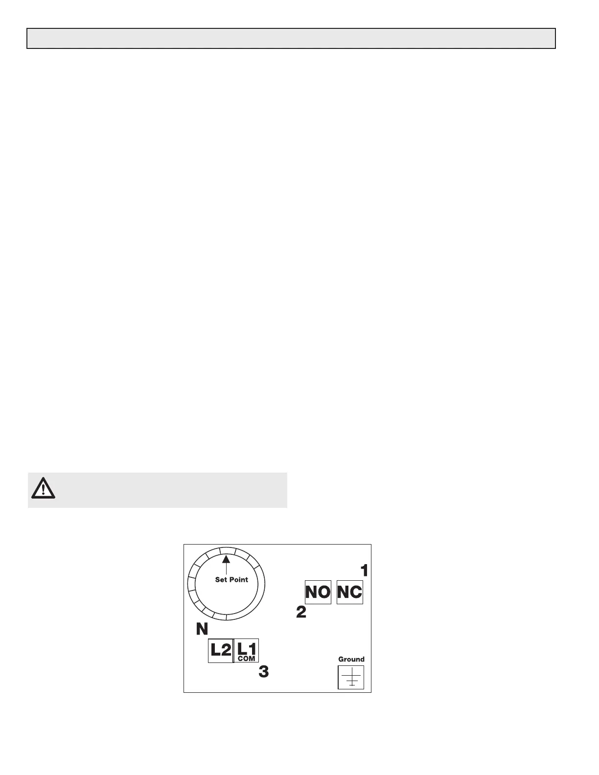
First, connect a meter capable of reading +/- 0 ohms to •
the NO and COM contacts, and verify that the NO and
COM contacts are made. Measure the resistance, and if
the resistance is more than 1 ohm, remove switch from
service. is more than 1 ohm. (See terminal illustration
below for guidance).
Then, verify that the low gas pressure switch will change •
state when a low gas condition is sensed by connect-
ing a meter capable or reading +/- 0 ohms to the NC
and COM contacts and then by causing the switch to
go into a fault condition. Once the fault occurs, Measure
the resistance, and if the resistance is more than 1 ohm,
remove switch from service. is more than 1 ohm.
To cause the fault, perform one of the two procedures:•
Turn the pressure switch setpoint counterclockwise 1.
until the switch trips.
Depressurize the volume of gas the low gas pressure 2.
switch is sensing. For FRI/6 regulators, this can be
done by opening the side tap on the oppositive side
of the FRI/6 regulator. For DMV and MBC safety
shutoff valves, this can be done opening the port
1 pressure tap. For SV valves, open port 1 of the
upstream valve.
Allow the burner to go through a startup sequence, and •
then verify that the burner faults and is not allowed to
light off.
Close all test taps (ports) and open upstream ball valve.•
When finished, close all pressure test points used, and •
then open the upstream ball valve SLOWLY to allow gas
pressure to gradually bleed into the system.
CAUTION: Opening the upstream ball valve too fast
can permanently damage the regulator.
High Gas Pressure Switch:
First, connect a meter capable of reading +/- 0 ohms to •
the NC and COM contacts, and verify that the NC and
Measure the resistance, and if the resistance is more
than 1 ohm, remove switch from service. is more than 1
ohm.
Then, verify that the high gas pressure switch will •
change state when a high gas condition is sensed by
connecting a meter capable or reading +/- 0 ohms to
the NO and COM contacts and then by causing the
switch to go into a fault condition.
To cause the fault, perform one of the two procedures:•
Turn the pressure switch setpoint clockwise until the 1.
switch trips.
Pressurize the volume of gas the high gas pressure 2.
switch is sensing. This can be done by closing the
downstream ball valve, opening port 3 tap on a DMV
and MBC safety shutoff valves, or port 2 or 3 of the
downstream SV valve, and then using a pump to
pressurize the test chamber.
Measure the resistance across the NO and COM •
contacts. If the resistance is more than 1 ohm, remove
switch from service.
Allow the burner to go through a startup sequence, and •
then verify that the burner faults and is not allowed to
light off.
When finished, close all test taps (ports) and open the •
dowmstream ball valve.
NOTE: A resistance of more than 1 ohm indicates
that the switch contacts are starting to either cor-
rode or carbonize.
Terminal Illustration
Do not similate fault conditions while the
burner is firing.
 Loading...