220736A,B INTERNAL AUXILIARY SWITCHES
63-2228—03 2
INSTALLATION
Disconnect power supply before beginning
installation to prevent electrical shock or
equipment damage.
NOTE: The wire colors of the 220736A,B auxiliary switches
are different from those of factory-installed auxiliary
switches (see Tables 1–3 and Fig. 2).
1. When replacing a Modutrol motor, determine original
motor model number and refer to Tables 1–3.
2. From the appropriate table, determine switch leadwire
color coding and configuration (N.O. and N.C. contacts).
3. For wiring convenience, make note of the difference
between the replaced motor and field addable switch
color coding.
4. Disconnect and remove the motor to be replaced.
5. Remove the cover from the wiring box of the
TRADELINE Modutrol IV motor.
6. Check motor for proper stroke setting. Adjust stroke as
needed. Refer to motor specification sheet.
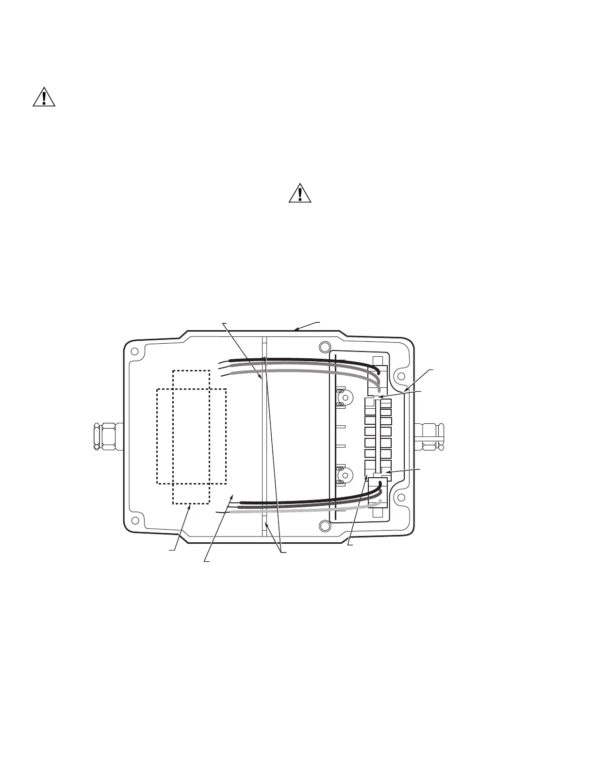
7. Position the switch assembly above the motor as shown
in Fig. 1.
8. Lower the switch assembly into place and tighten the
two mounting screws, making sure the switch followers
are properly aligned with the inner and outer cams in
the motor. The 220736A switch includes only the switch
for the outer cam.
9. Run all switch leadwires through slots to line voltage
section (at auxiliary end of motor), where connections to
auxiliary equipment should be made with solderless
connectors.
The auxiliary switches in the Series 91 low and
medium torque TRADELINE Modutrol IV motors
operate opposite to those in the Modutrol motors
listed in Tables 1 and 2.
When wiring the switches, connect the new switches
to the controlled equipment as shown in the
appropriate table.
Fig. 1. Position of auxiliary switch(es) in motor.
INTERNAL
AUXILIARY
SWITCH KIT
POWER
END
SLOTS (ROUTING SWITCH
LEADWIRES TO LINE
VOLTAGE SECTION)
M29140
RIGHT
SWITCH
FOLLOWER
INNER CAM
LEFT
SWITCH
FOLLOWER
MODUTROL IV WIRING BOX
VOLTAGE BARRIER
LINE VOLTAGE SECTION
TRANSFORMER
(CAN BE FIELD-ADDED)
 Loading...