3 … 4
• Remove the clear cover from the switch.
• Use 14 or 16 AWG wire rated for at least 75°C
• Route the wires through the conduit connector
• Connect the wiring to the appropriate screw terminals.
• Replace the clear cover from the switch.
WIRING
CAUTION: All wiring must comply with local electrical
codes, ordinances and regulations.
CAUTION: Do not exceed the switch ratings given in
the specifications and on the switch.
AA...A2 switching function
As pressure rises above
setpoint:
1 NC opens, 2 NO closes
As pressure falls below
setpoint:
1 NC closes, 2 NO opens
Adjusting the Set Point
• Remove the clear cover from the switch.
• Adjust the switch to the desired set point by turn-
ing the
dial. The white arrow on the dial indicates the set
point.
• After adjusting the set point, verifty that the pressure
switch operates as intended by using an accurate pres-
sure gauge connected upstream of the switch.
• Replace the clear cover.
Automatic Reset and Operation
The NC contact of the AA...A2 breaks when pressure rises
above the set point. It makes automatically when pressure
falls below set point.
ADJUSTMENT AND OPERATION
AA...A2-6 Threaded Connection
AA...A2-6 Mounting Procedure
• Apply good quality pipe sealant to the male threads only.
• Use 13/16” Wrench to secure the switch to the pipe.
DO NOT Exceed 45 lb-in of Torque on 1/8”
Connections
DO NOT Exceed 60 lb-in of Torque on 1/4”
Connections
• After installation is complete, perform a leak test.
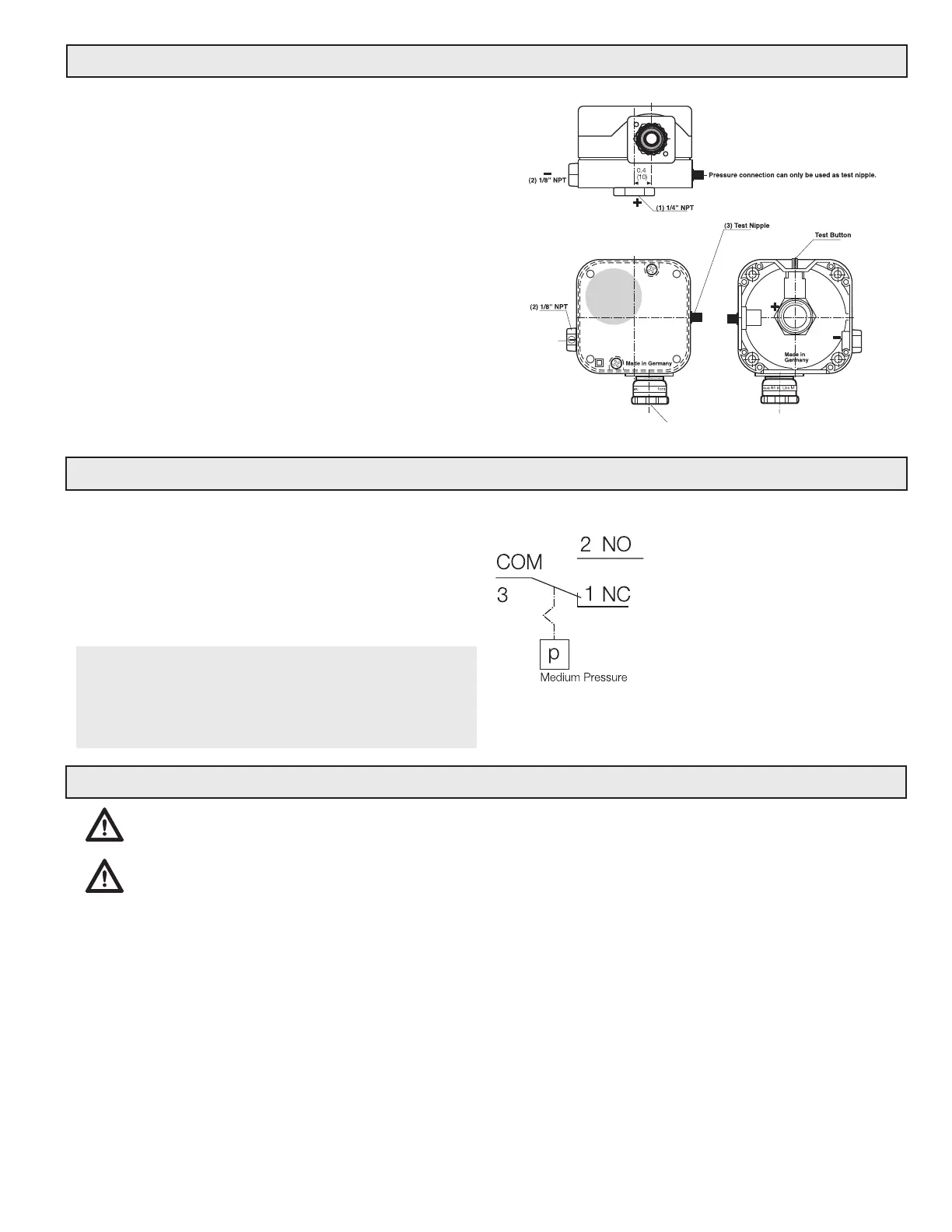
Test button (for AA-A2-6 series only)
When the test button is pressed the 1/4” NPT pressure con-
nection is interrupted and the pressure below the diaphragm
is relieved. The pressure switch changes the contact position
from NO to NC. When the test button is released, the pressure is
built up again and the switch changes to its original position.
(1) Pressure connection (+)
(2) Pressure connection (–)
(3) Test nipple p (+)
PRESSURE CONNECTIONS AND MOUNTING AA..A2-6
 Loading...