12
5 - COMBUSTION AIR/ VENT REQUIREMENTS
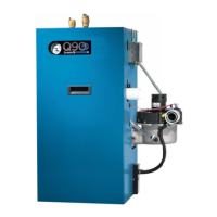
Figure 11 - Concentric Vent
3” Diameter PVC
Vent/Exhaust
1½”
4½” Dia.
31⅞”
A
A
B
B
C
C
D
E
F
G
G
3” Diameter PVC
Intake/Combustion Air
46¾”
Dimension
1
³⁄ΟΤ
”
D
E
F
Dimension
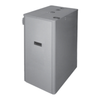
VENT
VENT
A
B
C
D
COMBUSTION
AIR
COMBUSTION AIR
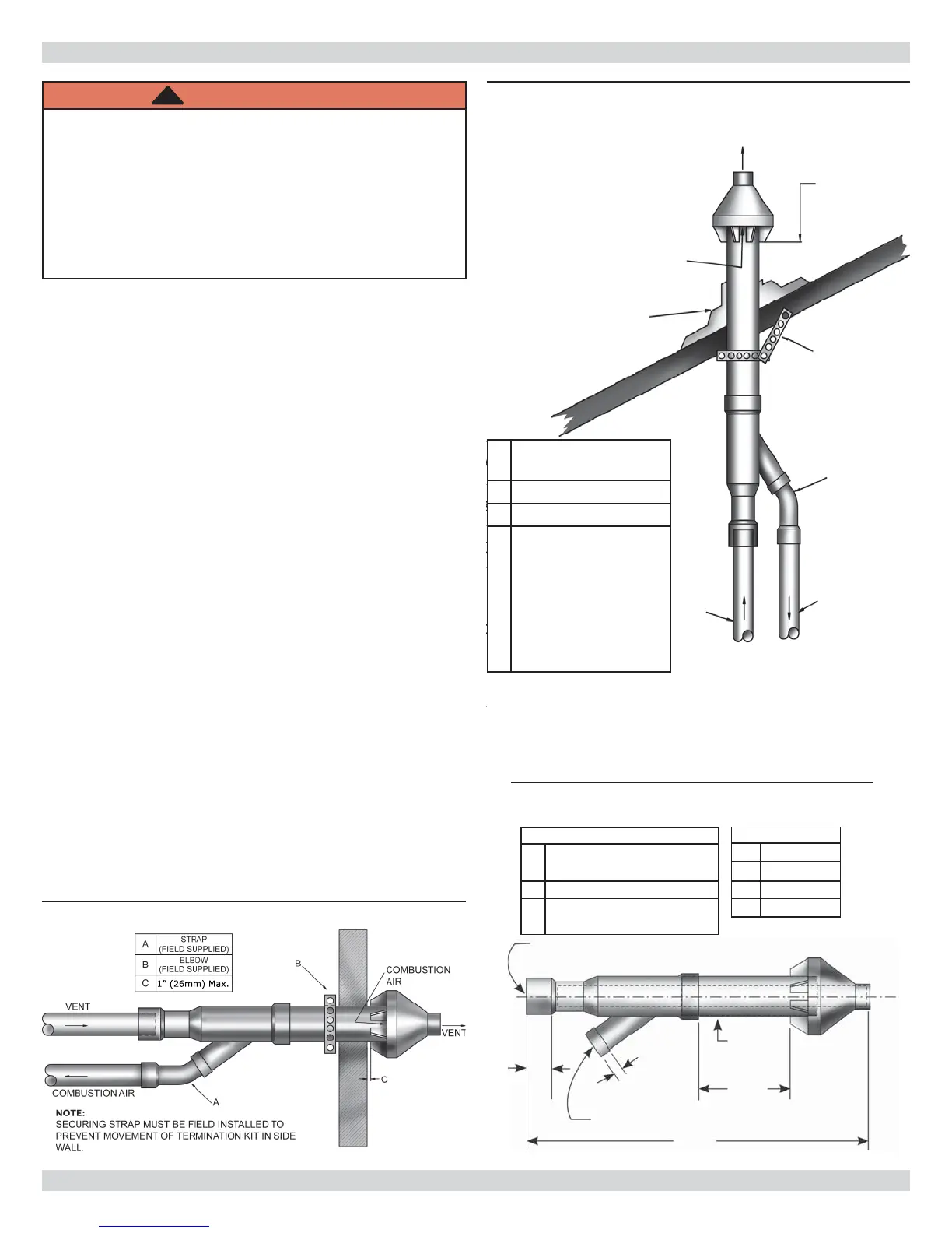
ROOF BOOT/FLASHING
(FIELD SUPPLIED)
ELBOW
(FIELD SUPPLIED)
SUPPORT
(FIELD SUPPLIED)
MAINTANIN 12 IN.
(18IN. FOR CANADA)
MINIMUM CLEARANCE
ABOVE HIGHEST
ANTICIPATED SNOW
LEVEL. MAXIMUM OF
24 IN. ABOVE ROOF
NOTE:
SUPPORT MUST BE
FIELD INSTALLED TO
SECURE TERMINATION
KIT TO STRUCTURE.
Figure 12 - Concentric Vent Roof Installation
• Covering non-metallic vent pipe and fi ttings with
thermal insulation shall be prohibited.
• Combustion air must be clean outdoor air. Do not take
combustion air from inside structure because that air
is frequently contaminated by halogens, which includes
fl uorides, chlorides, phosphates, bromides and iodides.
These elements are found in aerosols, detergents,
bleaches, cleaning solvents, salts, air fresheners, paints,
adhesives, and other household products.
• Locate combustion air inlet as far away as possible from
swimming pool and swimming pool pump house.
• All combustion air and vent pipes must be airtight and
watertight.
• Combustion air and vent piping must also terminate
exactly as shown in Figures 8 and 9.
• Use of concentric vent termination refer to Figures 10,
11 and 12 for proper setup.
• Vent connections serving appliances vented by
natural draft shall not be connected into any portion
of mechanical draft systems operating under positive
pressure.
WARNING
Fire, explosion, asphyxiation hazard. Solvent
cements are combustible. Keep away from heat,
sparks, or open fl ame. Use only in well ventilated
areas. Avoid breathing in vapor or allowing contact
with skin or eyes. Improper installation could result
in death or serious injury. Read this manual and
understand all requirements before beginning
installation.
!
A
Roof Boot/Flashing
(Field Supplied)
B
Elbow (Field Supplied)
C
Support (Field Supplied)
D
Maintain 12” (305mm),
18” (457mm)
Minimum Clearance
Above Highest
Anticipated Snow
Level.
Maximum of (610mm)
Above Roof.