9-5565-01
11
8
9
13
10
12 14
1
2 3 4 5 6
7
15
16
17
18
19
20
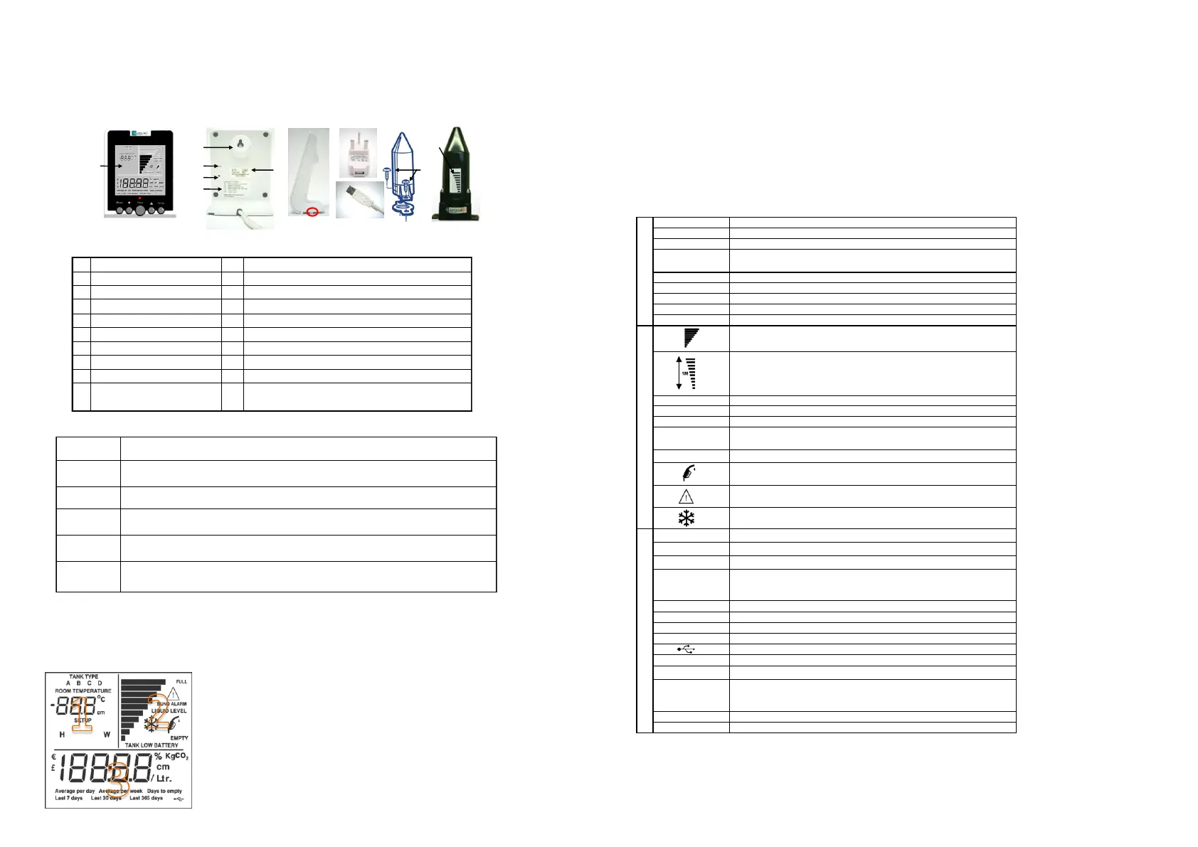
Apollo Smart features
1 LCD Display 11 Error code information
2 MODE key 12 Power/data cable
3 DOWN key 13 Manufacturing information
4 ENTER key 14
Location feature (see STEP 3 of the installation guide)
5 UP Key 15 USB connector
6 SETUP Key 16 Mains power plug
7 Alarm Red LED 17 Apollo Smart Transmitter
8 Wall mount feature 18 Self-tapping screws x 2
9 Beeper aperture 19 Weather seal (Gasket)
RESET access (pressing reset
erases all historical data.
20 Apollo Smart Transmitter oil level display
Indicates the Tank Type being selected
A, B, C are types of tank shapes (see diagrams in section 5)
The value displayed is the Room Temperature
Numeric display - Shows the Room Temperature in normal mode e.g 20.
Shows the Setup mode number when in setup mode, e.g. SETUP mode 3
The value displayed is temperature in degrees Celcius
The value displayed is in centimetres
The value displayed is the tank height
The value displayed is the tank width
Apollo Smart Monitor Display:
Bargraph indicator of liquid level - each bar represents 10% of tank height
Apollo Smart Transmitter Display:
Tanks 1m in height or greater - each bar represents 1/10th of the top meter of the tank.
Tanks less than 1m in height - each bar represents 1/10th of a metre
Indicates the 'Full' level of the bargraph indicator
Indicates the bargraph is showing the liquid level
Indicates the 'Empty' level of the bargraph indicator
When flashing there has been a leak into the 'Bund' (double skinned tanks).
The 10 bars and the RED LED will also be flashing at the same time.
The Apollo Smart Transmitter battery needs to be changed.
Flashing - The remaining liquid level in the tank is at 10% or below of tank height.
(Appears on both the Apollo Smart Monitor and Transmitter)
The value displayed is in Sterling pounds
The value displayed is in Euro
The value displayed is the % of usable oil remaining in the tank.
Numeric display - used to show numeric values and the time.
A numeric value is not available to be displayed when '---' is shown.
KgCO2
The value displayed is of Kg of CO2 (carbon emissions)
The value displayed is in centimetres
The value displayed is in Litres
The value displayed is per (litre)
The value displayed is the average per day based on the last 7 days usage
The value displayed is the average per week based on the last 14 days usage
The value displayed is the estimated number of days of oil remaining in the tank. It is
computed by dividing the volume of usable oil left in the tank by the current daily
average use.
The value displayed is the estimated usage over the last 30 days
The value displayed is the estimated usage over the last 365 days
Apollo Smart Monitor and Transmitter Display Symbol reference
The temperature is close to or below the limit of operation of the Apollo Smart
Transmitter - the information accuracy may be affected.
Flashing - There is a problem with the RF signal from the Apollo Smart Transmitter.
(Appears on both the Apollo Smart Monitor and Transmitter)
When in NORMAL mode press MODE to move between the current and the historical information screens.
Press UP to move between screens when in NORMAL mode.
Use it to increase a setting when in SETUP mode.
The ENTER key is used only in SETUP mode. It is used to save the setting shown on the display and then move
automatically to the next SETUP number.
Press DOWN to move between screens when in NORMAL mode.
Use it to decrease a setting when in SETUP mode.
Press SETUP for 3 seconds to enter SETUP. When in SETUP, press SETUP to exit from SETUP mode.
When in NORMAL mode, by pressing together and releasing, the screen will flash the current tank
configuration for 20 seconds. Press any key to return to NORMAL mode.
Apollo Smart Key Functions
2) APOLLO SMART – FEATURES AND FUNCTIONS
LED
The red light above the ENTER key flashes when there is an Alarm condition (see section 6) and on
receiving an RF signal from the Apollo Smart Transmitter
DISPLAY - SYMBOLS & INDICATORS
The Apollo Smart contains a display that conveys a variety of information during
normal use and during its initial setup and configuration for use with your oil
tank. The display contains three sections (1, 2, & 3) as indicated:
1 - Used for SETUP and displays SETUP number, and in normal use displays room temperature.
2 - Tank information including a visual bar-graph of the oil level in the tank.
3 - Information about the remaining usable oil in litres or as a %, the ‘Days to Empty’, and the average
and cumulative use of oil in litres, cost and KgCO
2
. Time is also displayed here.
 Loading...