6 | DOC-568_EN REV04 ORIGINAL INSTRUCTIONS
5. FLEXIBLE HOSE WITH ERGONOMIC HANDLE
At Duovac, we understand that your cleaning
experience with a central vacuum system
begins above all with the use of the exible
hose and accessories. This is why we o er
products above market standards, on top of
having unequalled advantages like the best
warranty in the industry.
Fig. 3 Low voltage technology handle
Your Duovac exible hose comes with a uniquely designed ergonomic handle, which makes its
use pleasant and worry free.
In your Duovac hose handle, you will nd the same quality, durability and solid design made
with rst-quality materials. The top-of-the-line nish of your Duovac exible hose is perfectly
harmonized with a series of accessories chosen by Duovac to make a perfect cleaning kit. The
performance, simplicity and durability are the three principles which led to the development
of your Duovac accessory kit. We are convinced that your cleaning experience will be improved
by it.
6� Connect the control module (see section 6)
7� Install the muffl er (optional);
8� Connect the power unit directly into an electrical outlet;
MUFFLER OPTIONAL
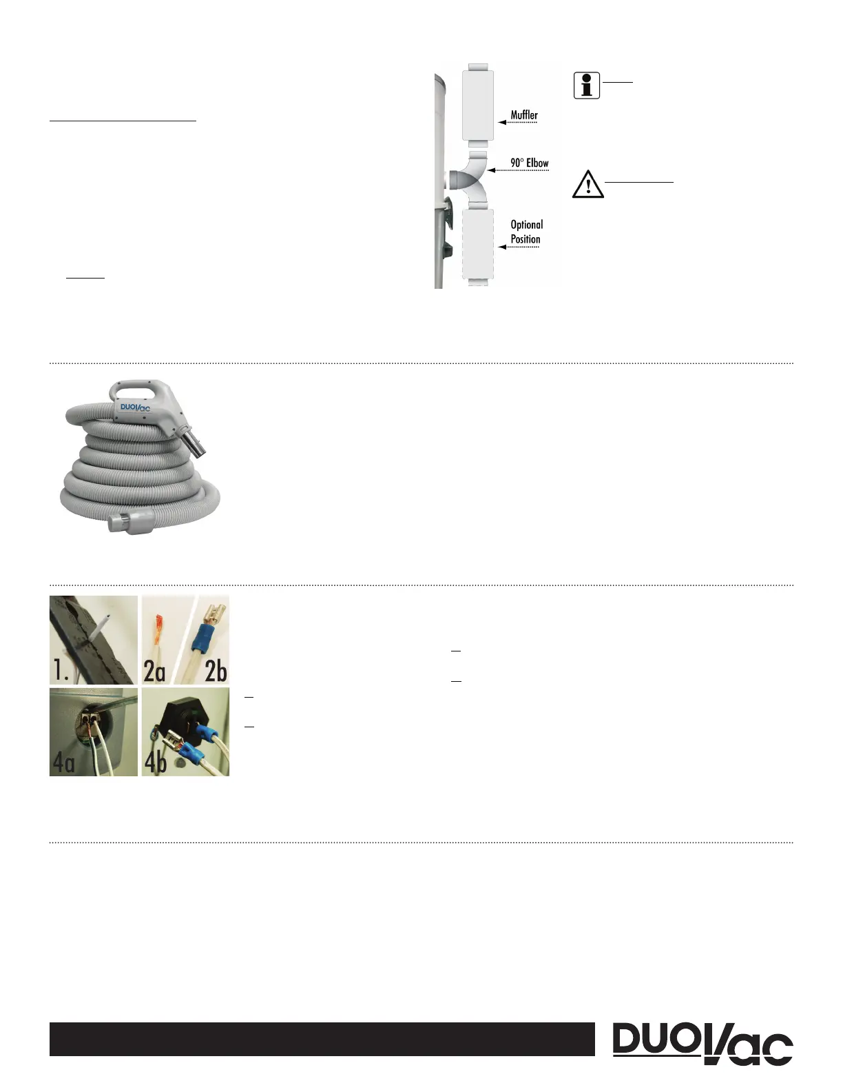
The installation of a muffl er is optional. Its purpose is to reduce the sound emitted by the
system. To install a muffl er on your power unit, follow these simple steps:
1� Turn o and unplug the unit;
2� Attach the 90° long elbow upwards or downwards onto the central vacuum outlet;
3� Secure the muffl er onto the elbow:
• If the inlet pipe of the muffl er is made of PVC, secure the muffl er onto the PVC elbow
using a PVC solvent glue;
• If the inlet pipe of the muffl er is made of metal, secure the muffl er onto the metal elbow
using the provided self-tapping screw;
4� OPTIONAL - If you plan on exhausting the central vacuum outside, install more piping
starting from the other end of the muffl er.
NOTE
» The muffl er can be oriented in the
direction of the exterior vent� The 90° elbow is
not mandatory�
» In case of space restriction around the power
unit, install the muffl er at any convenient
distance�
IMPORTANT
DO NOT use any plastic piping (e.g. PVC) along the
full length of the Distinction (2 serial-mounted motors)
central vacuumexhaust piping.
Fig. 2 Installing the mu er.
6. LOW VOLTAGE WIRE CONNECTION
Before connecting the low-voltage wires,
make sure that the power unit is disconnected
from the electrical outlet.
1� First, strip the low voltage wires
approximately 3/8in / 10mm.
2� Refer to Fig. 4 for visual aid:
• 2a: The power unit is an EZ connector-type,
leave the wires stripped.
• 2b: The power unit is a PIN connector-type,
you must crimp the connectors onto the wires
in order to hook-up the system.
Fig. 4 Low voltage wire connection
3� Insert the low-voltage wires into the power unit’s low voltage terminal. Slightly pull on
the low-voltage wires to verify that they are properly fastened to the terminal.
4� To remove the wires:
• 4a (EZ connector): Gently press the tabs above each terminal with a screwdriver and pull
the wires out.
• 4b (PIN connector): gently pull the connector out of the socket.
7. SYSTEM OPERATING INSTRUCTIONS
Your new system is ready to be used, here are some simple guidelines to follow when using your
power unit:
• Insert the exible hose in one of the wall or oor vacuum inlets installed in your home;
• If you use a hose tted with a remote switch on the handle, use the interrupter on the
hose’s handle to turn the power unit on/o .