13
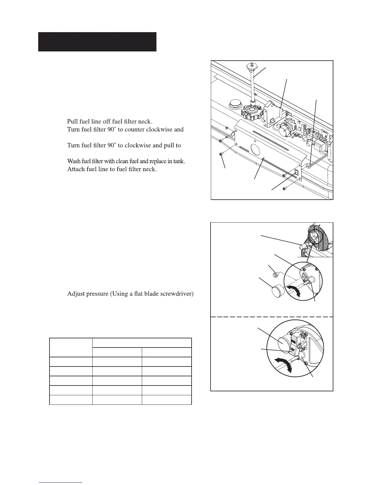
H.) FUEL FILTER
CLEAN OR REPLACE TWICE A HEATING
SEASON OR AS NEEDED.
- Remove side cover screws using medium
phillips screwdriver.
- Disconnect switch wires from power switch
and remove side cover.
-
-
pull to remove (DFA50/80T Models only).
-
remove (DFA135C/180CV/220CV Models only).
-
-
- Replace switch wires to power switch.
- Reinstall side cover.
I.) PUMP PRESSURE ADJUSTMENT
NOTE: If the pump pressure needs to be adjusted,
make sure the heater is running on the
HIGH BTU setting.
- Push the BTU CONTROL Switch to HIGH.
(See Operation, page 8, DFA180CV/220CV
Models only)
- Remove Pressure Gauge Plug from End Filter
Cover. Install accessory Pressure Gauge.
(DFA50/80T/135C Models only)
- Start heater (See Operation, page 8)
Allow motor to reach full speed
-
Turn relief valve to clockwise to increase
pressure. Turn relief valve to counter clockwise
to decrease pressure.
- Stop heater (See Operation, page 8)
NOTE: USE ONLY ORIGINAL EQUIPMENT
REPLACEMENT PARTS.
Use of alternate or third party components will
void any warranty and may cause unsafe
operating condition.
MODEL
Pump Pressure
High BTU level Low BTU level
DFA50 3.8 psi N/A
DFA80T 3.8 psi N/A
DFA135C 5.5 psi N/A
DFA180CV 6.5 psi 4.5 psi
DFA220CV 8.5 psi 6.5 psi
Figure 19. Fuel Filter Replacement
Figure 20. Adjusting Pump Pressure
NEVER LEAVE THE HEATER
UNATTENDED WHILE BURNING!
Fuel Filter
Fuel line
Switch Wires
Screw
Side Cover
Power Switch
Flat blade
Screw driver
DFA50/80T/135C Models Only
DFA180CV/220CV Models Only
Relief Valve
Relief Valve
Pressure Gauge
Pressure Gauge
Pressure Gauge Plug
End Filter Cover
BTU Control Switch
http://worldmkting.com/kerosene-forced-air-heater-tech-support
 Loading...