D-2
ELECTRICAL ADJUSTMENTS
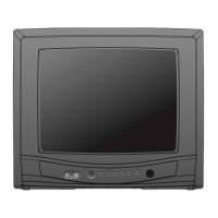
2-9: OSD HORIZONTAL
1.
2.
Activate the adjustment mode display of Fig. 1-1.
Press the VOL. UP/DOWN button on the remote
control until the difference of A and B becomes
minimum. (Refer to Fig. 2-3)
BA
TV
00 OSD 15
Fig. 2-3
2-10: VIF VCO
1.
2.
3.
4.
5.
Place the set with Aging Test for more than 10 minutes.
Receive an 80dB monoscope pattern.
Connect the digital voltmeter between the pin 5 of
CP601 and the GND.
Activate the adjustment mode display of Fig. 1-1 and
press the channel button (03) on the remote control to
select "V.VCO".
Press the VOL. UP/DOWN button on the remote control
until the digital voltmeter is 2.5V.
Receive an 70dB the color bar pattern.
Activate the adjustment mode display of Fig. 1-1
press the channel button (17) on the remote control
to select "CONT.MAX".
Press the VOL. UP/DOWN button on the remote control
until the contrast step No. become "40".
Press the TV/AV button on the remote to set to the
AV mode. Then perform the above adjustment 2.
Press the VOL. UP/DOWN button on the remote control
until the contrast step No. become "38".
1.
2.
3.
4.
5.
2-12: SUB CONTRAST
Receive an 70dB monoscope pattern.
Activate the adjustment mode display of Fig. 1-1 and
press the channel button (13) on the remote control to
select "BRI.CENT".
Press the VOL. UP/DOWN button on the remote control
until the screen begin to shine.
Press the TV/AV button on the remote to set to the
AV mode. Then perform the above adjustment 2, 3.
1.
2.
3.
4.
2-11: SUB BRIGHTNESS
2-8: VERTICAL SHIFT
1.
2.
3.
Receive the crosshatch signal from the Pattern
Generator.
Activate the adjustment mode display of Fig. 1-1
and press the channel button (07) on the remote
control to select "V.SFT".
Press the VOL. UP/DOWN button on the remote
control until the horizontal line becomes fit to the
notch of the shadow mask.
NOTE: Adjust after performing adjustments in section 2-7
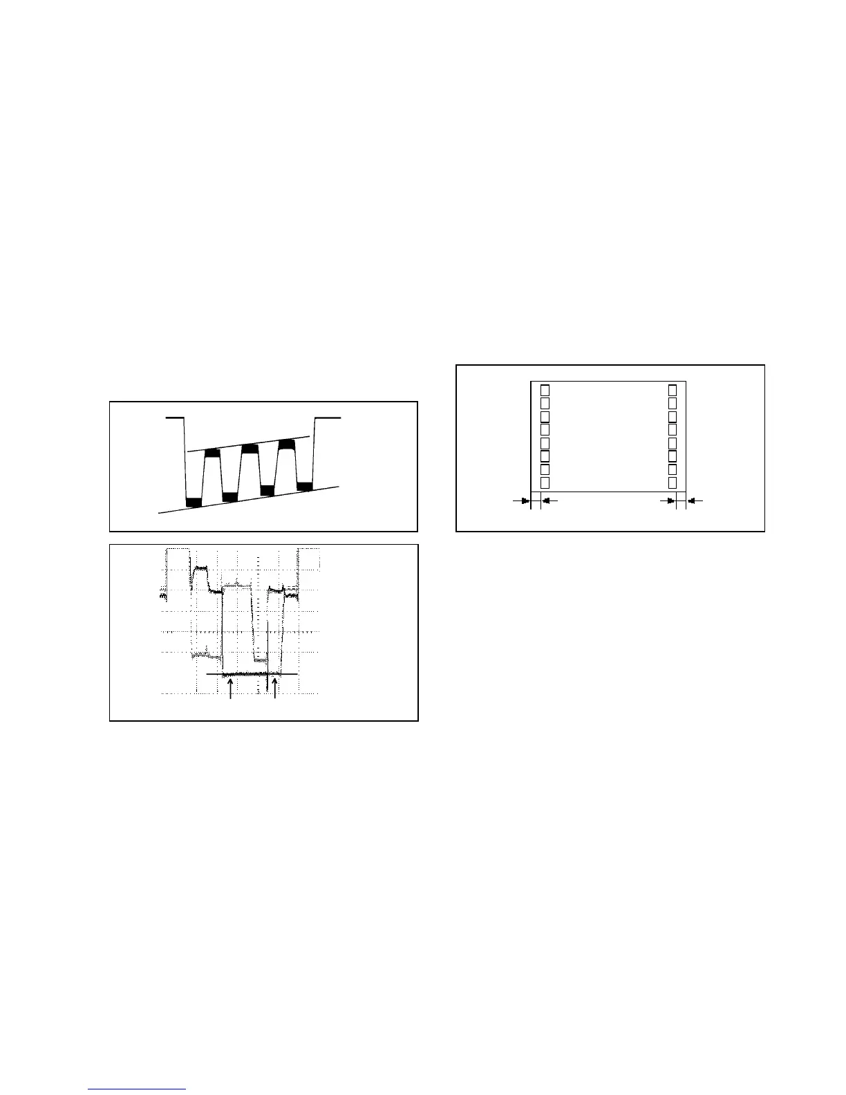
2-5: SUB TINT/SUB COLOR
1.
2.
3.
4.
5.
6.
7.
8.
9.
Receive the color bar pattern.
Connect the oscilloscope to TP023.
Activate the adjustment mode display of Fig. 1-1 and
press the channel button (22) on the remote control to
select "TINT".
Press the VOL. UP/DOWN button on the remote control
until the section "A" becomes as straight line
(Refer to Fig. 2-1)
Connect the oscilloscope to TP022.
Activate the adjustment mode display of Fig. 1-1 and
press the channel button (19) on the remote control to
select "COL.CENT".
Press the VOL. UP/DOWN button on the remote control
until the red color level is adjusted to 100% of the white
level. (Refer to Fig. 2-2)
Receive the color bar pattern. (Audio Video Input)
Press the TV/AV button on the remote control to set to
the AV mode. Then perform the above adjustments 2~7
Fig. 2-1
100%
white 100% red 100%
Fig. 2-2
"A"
2-7: VERTICAL SIZE
1.
2.
3.
4.
Receive the crosshatch signal from the Pattern
Generator.
Activate the adjustment mode display of Fig. 1-1 and
press the channel button (06) on the remote control to
select "V.SIZE".
Press the VOL. UP/DOWN button on the remote control
until the SHIFT quantity of the OVER SCAN on upside
and downside becomes 10 ± 2%.
Receive a broadcast and check if the picture is normal.
NOTE: Adjust after performing adjustments in section 2-6
2-6: HORIZONTAL PHASE
1.
2.
3.
Receive the center cross signal from the Pattern
Generator.
Activate the adjustment mode display of Fig. 1-1 and
press the channel button (05) on the remote control to
select "H.PHAS".
Press the VOL. UP/DOWN button on the remote
control until the SHIFT quantity of the OVER SCAN on
right and left becomes minimum.