EasyManua.ls Logo

DURASTAR DRAM36S1A - User Manual

Default Icon
56 pages
Print Icon
To Next Page IconTo Next Page
Loading...
R
DURASTAR.COM1
INSTALLATION MANUAL
AIR HANDLER UNIT: 30K to 60K
DRAM30S1A, DRAM36S1A, DRAM48S1A, DRAM60S1A
FILTER COVER
Model Number:
Serial Number:
Purchase Date:
Installing Contractor Company Name:
208/230V 1ph 60 HZ 24V / RS485 Communicating
NOTE
This manual only refers to the models listed above. If you are installing the DRAM18F1A or
DRAM24F1A please refer to the manual included with that unit.
TIP
Capture relevant information about your Durastar mini-split equipment before it is
installed and write it above for future reference.
Question and Answer IconNeed help?

Do you have a question about the DURASTAR DRAM36S1A and is the answer not in the manual?

Summary

Installation Manual

Air Handler Unit Specifications

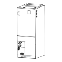
Identifies the unit as an air handler with a capacity range of 30K to 60K.

Important Safety Precautions

Operation, Cleaning, and Maintenance Safety

Details safety rules for using and maintaining the air handler unit.

Electrical Safety

Electrical Work Safety Precautions

Provides crucial safety guidelines for all electrical and wiring work.

Installation Safety

Installation Preparation

Air Handler Installation

Duct Requirements

Condensate Piping Installation

Refrigerant Piping Connection

Refrigerant Piping Specifications

Lists specifications for refrigerant piping based on unit capacity.

Oil Traps

Refrigerant Pipe Connection Instructions

Connecting Pipes

Connecting Piping Procedure

Procedure for connecting the refrigerant pipes, including torque specifications.

Insulate Refrigerant Fittings

Wiring Overview

Electric Heater Installation (Optional)

Auxiliary Heater Installation

Confirm Electric Heater Wiring

Wiring Confirmation Checklist

Procedure to verify electric heater wiring connections before powering on.

Electric Auxiliary Heating Wiring Diagrams

5 KW Wiring Diagram

Wiring diagram specific to the 5KW electric auxiliary heater.

8 KW;10 KW Wiring Diagram

Wiring diagram for 8KW and 10KW electric auxiliary heaters.

15 KW Wiring Diagram

Wiring diagram specific to the 15KW electric auxiliary heater.

Indoor Unit Wiring

Connect the Signal Cable

Explains how to connect the signal cable for indoor/outdoor unit communication.

Wiring the Communication Cable

Wiring Connection Methods

Method 1: RS485 + 24 V Thermostat

Details wiring for RS485 communication with a 24V thermostat.

Method 2: RS485 Communication

Details wiring for RS485 communication with the DRSTAT100 wired controller.

Method 3: 24 V Communication

Details wiring for full 24V communication.

Control Logic

Indoor Unit Connector Purposes

Lists and describes the purpose of each connector terminal on the indoor unit.

Outdoor Unit Connector Purposes

Lists and describes the purpose of each connector terminal on the outdoor unit.

Thermostat Wiring Diagrams

Multi-Stage Thermostat Wiring

Diagrams for 4H/2C, 3H/1C, 3H/2C, 2H/2C, 2H/1C thermostats.

Single-Stage Thermostat Wiring

Diagram for 1H/1C thermostat setup.

LED Display Definitions

DIP Switches Settings and Configuration

DIP Switch Definitions

SW1-SW4 Switch Definitions

Provides detailed definitions for each DIP switch and their functions.

Function DIP Switch Settings

S3 Rotary Switch Configuration

Explains the S3 rotary switch for setting temperature protection.

SW4 DIP Switch for Airflow;Heater

Explains the SW4 DIP switch for air flow and heater settings with a 24V thermostat.

Air Volume Table

Air Volume Table (Continued)

Power Specifications

Final Checks

Gas Leak Check Points

Test Run

Troubleshooting

Safety Precautions

Immediate actions to take if critical conditions occur.

Troubleshooting Performance Problems

Wiring Diagram

Error and Operating Codes

DURASTAR DRAM36S1A Specifications

General IconGeneral
Airflow Capacity1200 CFM
Motor TypePSC
Voltage208/230V
Cooling Capacity (BTU)36000 BTU
Cooling Capacity3 Ton

Related product manuals