Do you have a question about the DURASTAR DRAM30S1A and is the answer not in the manual?
Explains symbols for warnings, notes, and tips to guide user understanding.
Details safety guidelines for operating, cleaning, and maintaining the air handler unit.
Provides critical safety information and warnings before performing electrical or wiring work.
Ensures safe installation practices and adherence to regulations for preventing hazards.
Specifies the recommended indoor and outdoor temperature ranges for optimal air handler operation.
Lists both included and separately purchased accessories for installation.
Lists required tools and provides physical dimensions for different model BTU capacities.
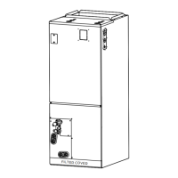
Details filter specifications and identifies key unit components with a diagram.
Guidelines for choosing an appropriate location for the indoor unit, including do's and don'ts.
Specifies clearance requirements for both horizontal and vertical installation orientations.
Illustrates airflow directions and highlights secondary drain pan recommendations.
Instructions for removing the filter, upper cover, and evaporator cover plate.
Instructions to unplug sensors/EEV and adjust wire ties for cable slack.
Instructions for removing evaporator/drain pan and adjusting the mounting bracket.
Instructions to rotate coil, reinstall evaporator/pan, and re-tie sensor wires.
Instructions to secure sensor wire and reinstall evaporator/filter cover plates.
Covers ductwork, piping, optional heater, devices, and test run considerations.
Guidelines for ductwork, sealing, and warnings about return air sources.
Instructions for condensate drainage, sealing, and secondary drain pan requirements.
Illustrates drain hole locations, trap configuration, and drainpipe outlet clearance warnings.
Table detailing refrigerant connection sizes, pre-charged refrigerant, and piping length limits.
Explains the necessity and placement of oil traps for systems with significant height differences.
Steps for cutting, deburring, and flaring refrigerant pipes for leak-free connections.
Details flare extension, torque values, and visual guides for correct flare dimensions and shapes.
Instructions for connecting pipes, including bending radius, oil application, and tightening.
Provides torque, flare dimensions, and instructions for insulating refrigerant fittings.
Covers power wiring schematics and guidelines for optional electric heater installation.
Details heater compatibility, electrical data, and step-by-step installation instructions.
Instructions for removing covers, installing assembly, and connecting heater wiring.
Instructions for installing covers and applying the circuit breaker label.
Final checks to ensure wiring connections are secure and wire size is correct.
Provides detailed wiring diagrams for various electric auxiliary heating module capacities.
Guidance on signal cable prep, routing, sizing, and accessing the control box.
Steps for connecting power and signal cables to the terminal block.
Contains warnings on power isolation and 24VAC connections, and SW1 DIP switch default.
Details wiring configurations for RS485 and 24V communication methods with thermostats/controllers.
Details the purpose of connector terminals on both indoor and outdoor unit control boards.
Provides wiring diagrams for multiple thermostat configurations (e.g., 4H/2C, 3H/1C) with air handler.
Table defining LED display states for various operating modes, priorities, and fan speeds.
Provides a guide to DIP switch settings and maps them to control scenarios.
Defines the functions of various DIP switches related to operation modes, timing, and adjustments.
Explains the S3 rotary switch for temperature protection and SW4 for air flow/heater settings.
Tables showing airflow volumes (CFM) based on fan speed, heater kit, and control settings.
Tables showing airflow volumes (CFM) based on fan speed, heater kit, and control settings.
Instructions for connecting condensate overflow switches and utilizing the alarm output.
Wiring for humidifier, dehumidification control via humidistat, and UV LED connections.
Tables detailing electrical specifications (MCA, MOCP, voltage, FLA) for indoor and outdoor units.
Covers test run importance, pre-run checklist, electrical checks, and gas leak detection methods.
Identifies leak check points and provides step-by-step instructions for performing the unit test run.
Safety precautions and troubleshooting for common issues like mode changes or unit startup problems.
Addresses common issues like unit noises, odors, fan operation, and system responsiveness.
Troubleshooting for poor performance, flashing lamps, error codes, or unit failure.
Detailed diagrams showing connections to the indoor mainboard and outdoor unit.
Comprehensive list of error and operating codes for indoor/outdoor units and system protection.
| Cooling Capacity | 30, 000 BTU/h |
|---|---|
| Voltage | 208/230V |
| Phase | 1 |
| Frequency | 60 Hz |
| Heating Capacity | 30, 000 BTU/H |
| Motor Type | PSC |
| Airflow | 1, 200 CFM |