R
DURASTAR.COM
33
INDOOR UNIT WIRING
Connect the Signal Cable
The signal cable enables communication between the indoor and outdoor units. You must first
choose the right cable size before preparing it for connection. Run a continuous length of cable and
avoid splicing the cable.
Cable Sizing
Use the correct size cable depending on the communication type (see page 35)
• Non-polar RS485 Communication (S1/S2): 16 AWG stranded, shielded
• 24V Communication: 18 AWG/ 8 conductor thermostat wire
• Power Cables: Determined by the minimum circuit ampacity (MCA) and maximum over current
protection (MOCP) of system and the NEC and local codes in your area. Refer to the nameplate
to choose the right cable, fuse, or switch.
STEP 1. PREPARE THE CABLE FOR CONNECTION.
• Using wire strippers, strip the insulating jacket from both ends of the signal cable to reveal about 5
in (12 cm) of the wire, then strip the insulation from the ends of the wires.
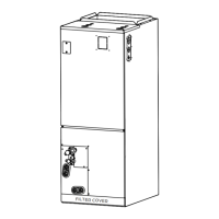
STEP 2. OPEN THE FRONT PANEL OF THE UNIT.
• Using a screwdriver, remove the cover of the electric control box on your indoor unit.
STEP 3. CONNECT THE WIRES TO THE TERMINALS.
• Thread the power cable and the signal cable through the wire outlet.
• Match the wire colors/labels with the labels on the terminal block. Firmly screw the wires of each
wire to its corresponding terminal. Refer to the Serial Number and Wiring Diagram located on the
cover of the electric control box.
WARNING
While connecting the wires, strictly follow the wiring diagram, and refer to the
nameplate for electrical information. Wire according to NEC and local codes.
The refrigerant circuit can become very hot. Keep the interconnection cable
away from the copper tube.
WARNING
Failure to follow warnings may lead to equipment damage, injury or death.
Field line side wires may remain live, DO NOT perform service or maintenance
until the main disconnect is pulled.
 Loading...